
c. Cleaning.
Refer to paragraph 4-21 for
d. Inspection. Check the components for
cleaning instructions.
wear limits as specified in table E-7.
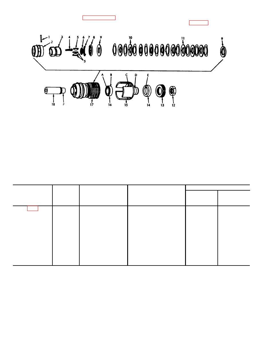
1 - PIN
10 - DISK
2 - SLEEVE
11 - DISK
3 - CLUTCH BODY
12 - LOCKNUT
4 - CLUTCH DOG ASSEMBLY
13 - NUT
5 - KEY
14 - BEARING
6 - SPLIT RING
15 - CUP
7 - LOCK SPRING
16 - BEARING
8 - COLLAR
17 - CLUTCH ASSEMBLY
9 - PLATE
18 - SHAFT
Figure E-17. Disassembly or assembly of clutch assembly and related components.
Table E-7. Repair and Rebuild Standards for Clutch Assembly
and Related Components
Wear Limits
Direct and
Fig
Ref
Point of
Size and Fit
General
No
Letter
Measurement
of New Parts
Support
Depot
A
ID of Bearing
1.3775 to 1.3780
(*)
(*)
E-19
B
OD of Bearing
2.8341 to 2.8346
(*}
(*)
E-19
C'
ID of Bearing
2.8346 to 2.8334
(*)
(*)
Recess in Spider
E-19.
B-C
Fit of Bearing
0.0000 to 0.0007 T
(*)
(*)
in Recess
E-19
D
OD of Spider Spindle
1.9686 to 1.9690
(*)
(*}
E-19
E
ID of Bearing
1.9680 to 1.9685
(*)
(*)
E-19
F
OD of Shaft
1.3770 to 1.3776
(*)
(*}
E-19
A-F
Fit of Shaft in Bearing
0.0001T to 0.001L
(*)
(*)
E-19
D-E
Fit of Spindle
0.0001T to 0.001T
(*)
(*)
in Bearing
e.
Assembly
(2) Fit two split rings into groove in shaft.
(3) Slide thrust plate into shaft and over
(1) Tap 3 keys into slots in shaft. Keys
the keys and split rings.
should fit tightly and not rock. If installing new keys,
grind lightly, if necessary, to obtain proper fit.
AE-22
