
TM 9-3405-206-14 & P
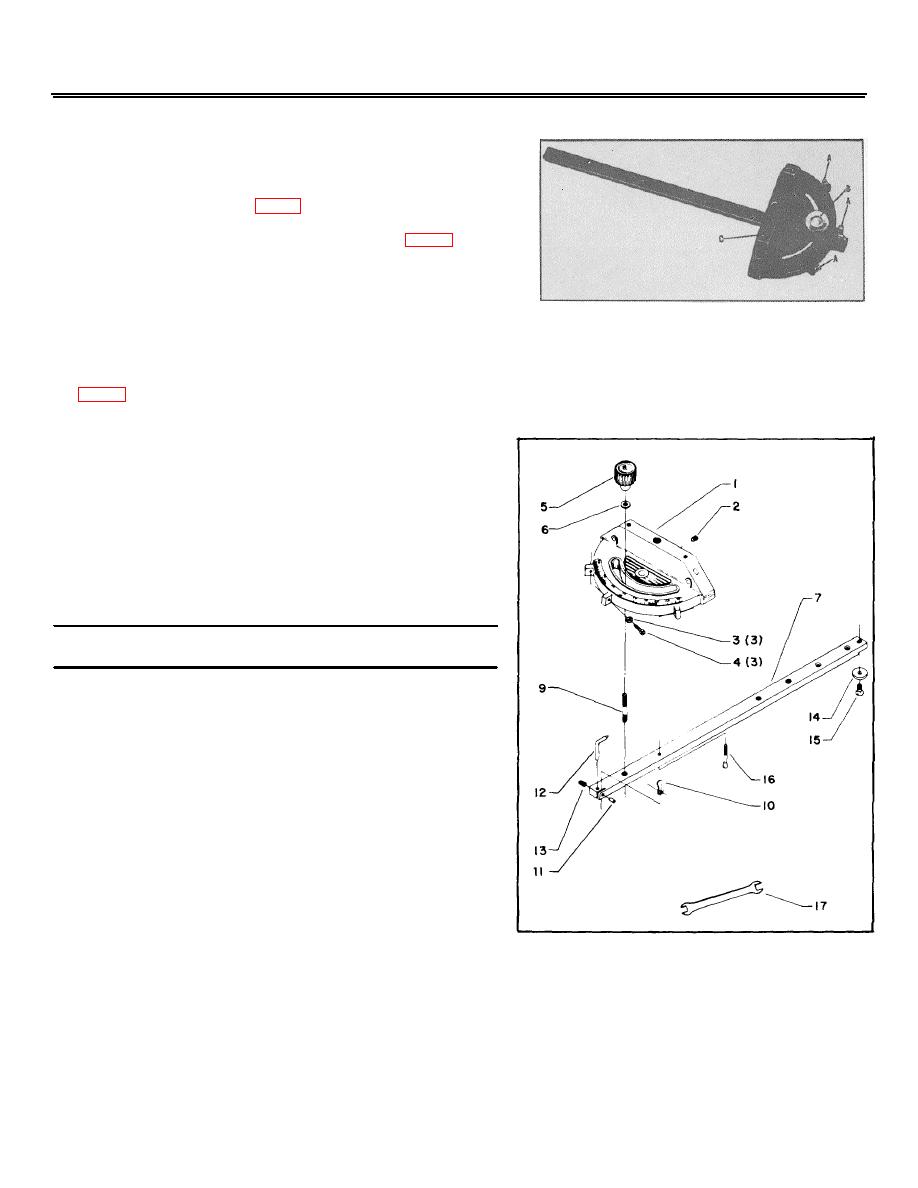
34-895 MITER GAGE
Miter Gage is accurately constructed and equipped with individually
adjustable index stops at 90 degrees and 45 degrees right and left.
Adjustment to the index stop can be made by tightening or loosening
the three adjusting screws (A) Fig. 1.
To operate the miter gage, loosen the lock knob (B) Fig. 1, and move
the body of the miter gage (C) to the desired angle. The miter gage
body will stop at 0 degrees and 45 degrees both right and left. To
rotate the miter gage body past these points, the stop link (ref. #10)
Fig. 2, must be flipper out of the way.
Fig. 1
The head of the miter gage pivots on a special tapered screw that fastens the head of the miter gage to the bar. If the
miter gage head does not pivot freely or after long usage pivots too freely, it can be adjusted by loosening setscrew (ref.
#2) Fig. 2, and turning the tapered screw (ref. #16) in or out. Be sure to tighten setscrew (ref. #2) after adjustment is
made.
IMPORTANT: THE SPECIAL PLATE (ref. #14) AND FLATHEAD
SCREW (ref. #15) FIG. 2, ARE USED WHEN THE MITER GAGE
IS USED ON CIRCULAR SAW TABLES THAT ARE EQUIPPED
WITH T-SLOT MITER GAGE SLOTS. FOR PRODUCTS NOT
EQUIPPED WITH T-SLOT MITER GAGE SLOTS, THESE ITEMS
ARE TO BE REMOVED.
Replacement Parts
Ref.
Part
Description
No.
No.
Cat. #34-895
Miter Gage, Consisting of:
1
NCS-160-A
Miter Gage Body, including:
2
NCS-177
Special Setscrew
3
NCS-173
Special Nut
4
SP-723
#9-32 X 1/2" Fil Hd. Scr.
5
NCS-164
Lock Knob
6
DSS-79
Fiber Washer
7
422-04-004-0001
Bar
9
NCS-166
Stud
10
NCS-170
Stop Link
11
NCS-171
Special Pin
12
NCS-174
Pointer
13
NCS-177
Special Setscrew 2
14
422-04-072-0001
Plate
15
SP-5750
1/4-28 X 5/16" Flat Hd. Mach. Scr.
16
NCS-168
Special Pivot Screw
17
Cat. #1522
Wrench
33
