
TM 9-3405-215-14&P
UNIVERSAL CALIBRATED WORK FIXTURE
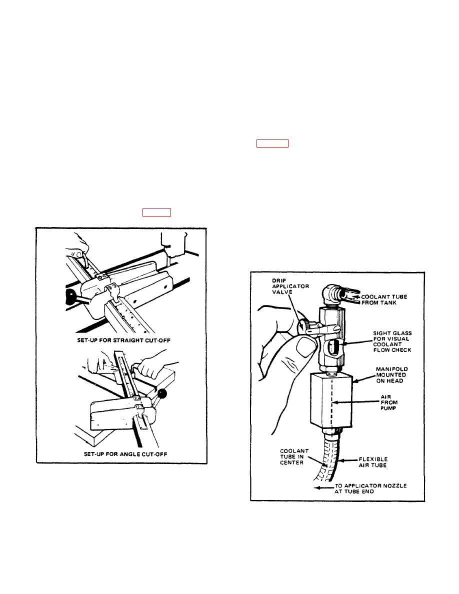
machine head back to drip applicator valve with sight
glass. Coolant next enters manifold and is directed into
This accessory clamps to the table, can be set up for
a nylon tube which passes through flexible air tube. Air
straight or angle cut-off, and holds the workpiece in
and coolant are mixed at nozzle end to form a fine mist.
position while it is moved into the saw band. For straight
Bend applicator tube to direct mist stream onto blade
sawing, place fixture on table at required distance from
teeth and work.
band. Loosely install T-nuts and screws. Square fixture
to table by lining up one moveable stop edge with one
Regulate mist with drip applicator valve. Count drops
table slot edge. Tighten screws. Saw kerf into bar 1/16
visible through sight glass. Normal mist adjustment
to 1/8 inch (1.5 to 3.2 mm) deep to allow cutting
produces approximately one coolant drop per second.
completely through workpiece. Set adjustable table
See Fig. 33. Check for a fine, consistent mist by
stops to prevent deeper sawing into work bar after cut
directing stream onto a metal surface. Intermittent
completion.
stream with coolant spurts generally indicates a manifold
air leak. Check all joints.
For angle sawing, remove right T-nut and screw.
Loosen left screw, turn fixture to desired angle, and
Clean nozzle and coolant bottle when necessary.
tighten left screw. Mount collar (behind bar) loosely on
Replace nylon center tube by disassembling flexible
T-nut with socket-head screw.
Bring collar snugly
tubing. Insert new center tube. Make sure all joints are
against bar and tighten screw. See Fig. 32.
sealed and tight. Coil applicator tube a few times, and
trim excess nylon so that it is flush with nozzle end.
See Lubrication Chart for recommended coolant
products. Clogging may occur if wax-based or other
coolants are used.
FIG. 32. UNIVERSAL CALIBRATED WORK FIXTURE.
MIST COOLANT APPLICATOR
Coolant is delivered from a 1-quart (0.95-liter) bottle on
FIG. 33. ADJUSTING MIST COOLANT.
20
