bracket slightly and reposition against stop pin. Check
this alignment. To align centers, mount a dial indicator on
position on indicator. Traverse table back and forth. Dial
the wheel guard support shaft and let the indicator touch
indicator should not vary more than .002.
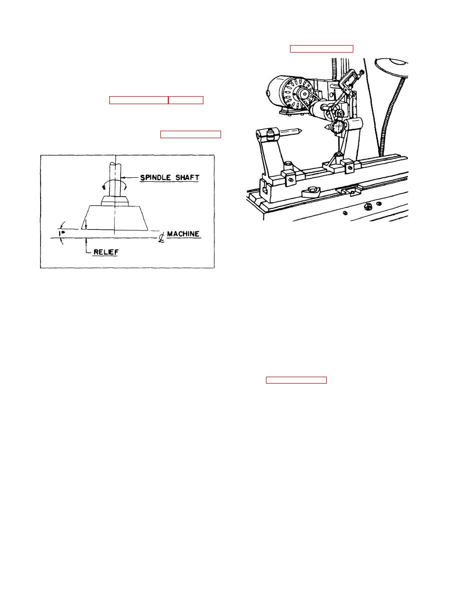
the centers. See Illustration No. 5.
The grinding wheel spindle and column should
next be adjusted to permit grinding wheel relief. Loosen
hex cap screws (dia No. 36 of exploded view drawing No.
2) and rotate column toward front of machine when work-
head is used as shown in Illustration No. 2 and No. 3.
The object here is to relieve the cup wheel so that
it will not drag on the surface just ground by the leading
edge of the grinding wheel. See drawing illustration No. 4.
ILLUSTRATION NO. 5
LINING UP THE CENTERS
Do not tighten hold-down screw (dia No. 8 and No. 9).
Leave them slightly loose so that the sub-table can be
moved or rotated about the shoulder screw. Next, move
ILLUSTRATION NO. 4
the sub-table back and forth as required to achieve an
RELIEVING THE GRINDING WHEEL
indicator reading of (.001) one thousandth. Tighten the
sub-table hold down screws and re-check dial indicator
HEIGHT SCALE
reading. Now the center stand can be positioned to
receive the work to be ground. If desired, a scribed line
The height scale should be set so that the pointer reads
may be placed on the right hand end of sub-table and the
"O" when the center of the grinding wheel spindle is at the
grinder table if these lines are carefully made, it will not be
same elevation as the center of the work-head collet
necessary to re-indicate sub-table each time it is used for
adapter. This will permit setting the grinding wheel at the
most applications. For very close work, the table should
proper height when grinding relief angles on the outside
always be indicated in for each job. When grinding work
diameter of some cutters.
with a taper, the sub-table can be rotated as needed up to
45. See illustration No. 6.
CENTER STANDS AND SUB-TABLE
GRINDING WHEELS
The sub-table is mounted directly on top of the grinder
table using the shoulder screw (dia No. 8 of exploded view
The 374 Router Bit Grinder uses either two or three inch
drawing No. 4) and two (2) hex cap screws and washer
diameter grinding wheels and in resinoid or vitrified bond.
(dia No. 9 and No. 11.)
It is important to always use grinding wheel blotters with
these grinding wheels. A blotter should be placed on both
The center stands can be positioned anywhere along
sides of the grinding wheel. In the case of diamond
the sub-table, depending on work to be ground. When
grinding wheels, no blotters are necessary and should not
placing center stands on the sub-table, always snug up on
be used. When tightening the
the take-up tabs (dia No. 5) before you tighten hold-down
screws (dia No. 10). This will permit the center stands to
guide on one side of the machined T-slot and, after
alignment, the center stands can be moved without losing
4


