OPERATION (Cont'd)
vented by a slip clutch. A loud sound produced by this
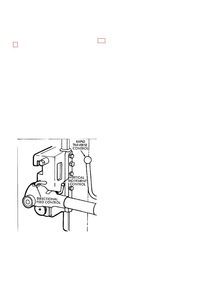
ADJUST RAPID TRAVERSE
clutch warns of reaching the limit.
Horizontal and vertical rapid traverse is always
available whether the machine is running or idle, as long
NOTE: This clutch does not protect the machine at
as the motor is operating. Traverse is engaged by
pulling outward on the rapid traverse control. (See Fig.
the upper limit of vertical traverse. Caution
should therefore be exercised in positioning
the directional feed control and is indicated on an
the crossrail to prevent damage to the ram
adjacent plate.
or tool head.
To traverse horizontally: Place the directional feed
control in the direction desired (jogging the rapid
To traverse vertically: First loosen table support
traverse control handle to engage clutch teeth) and
clamp and remove the stress block. Then loosen the
place the vertical movement control in its lower position
rail clamp (F) and revolve rail clamp (G) several
(which is the standard position for feeding and
revolutions counterclockwise. (Do not loosen the jam
traversing horizontally). Pull outward on the rapid
nuts because they are adjusted to hold the crossrail
traverse control to traverse.
slideably to the frame.) Place the directional feed control
in the vertical traverse direction desired (jogging the
THE DIRECTION OF HORIZONTAL RAPID
rapid traverse control handle to engage clutch teeth)
TRAVERSE IS ALWAYS OPPOSITE TO THE
and place the vertical movement control in its upper
DIRECTION OF THE FEED SET. Releasing the control
position. Pull outward on the rapid traverse control to
disconnects the traverse and automatically reinstates
traverse. Releasing the control disconnects the traverse
the feed.
mechanism.
Always place directional feed control in neutral
The table is raised or lowered by rapid traverse to
when positioning work table horizontally by hand to
its approximate working position. This position should
avoid damaging the feed mechanism. Overtravel past
be as high as possible consistent with safety so as to
either end limit of horizontal rapid traverse or feed is
minimize overhang of tool. Final adjustment of the tool
pre-
in relation with the work is made by setting the tool
head.
When table is in position place vertical movement
control in its lower position, then secure rail with clamp
(F) and rail clamp (G), reset table support and adjust
stress block to lock the front of the table.
ADJUST FRONT SUPPORT
On machines equipped with a front support, always
use both the support and the stress block. After
clamping the front support, insert the stress block
directly under the table on the inside of the front
support. If the table is set at or near its lowest position,
or if machine is equipped with a universal table, the
stress block will not fit beneath the table and should be
applied to the clamp outside of the support.
The vise may be swiveled by loosening the four
clamping bolts of bottom plate. Tighten bolts securely
before beginning to shape.
Figure 2.
4

