
TM 9-3431-254-14&P
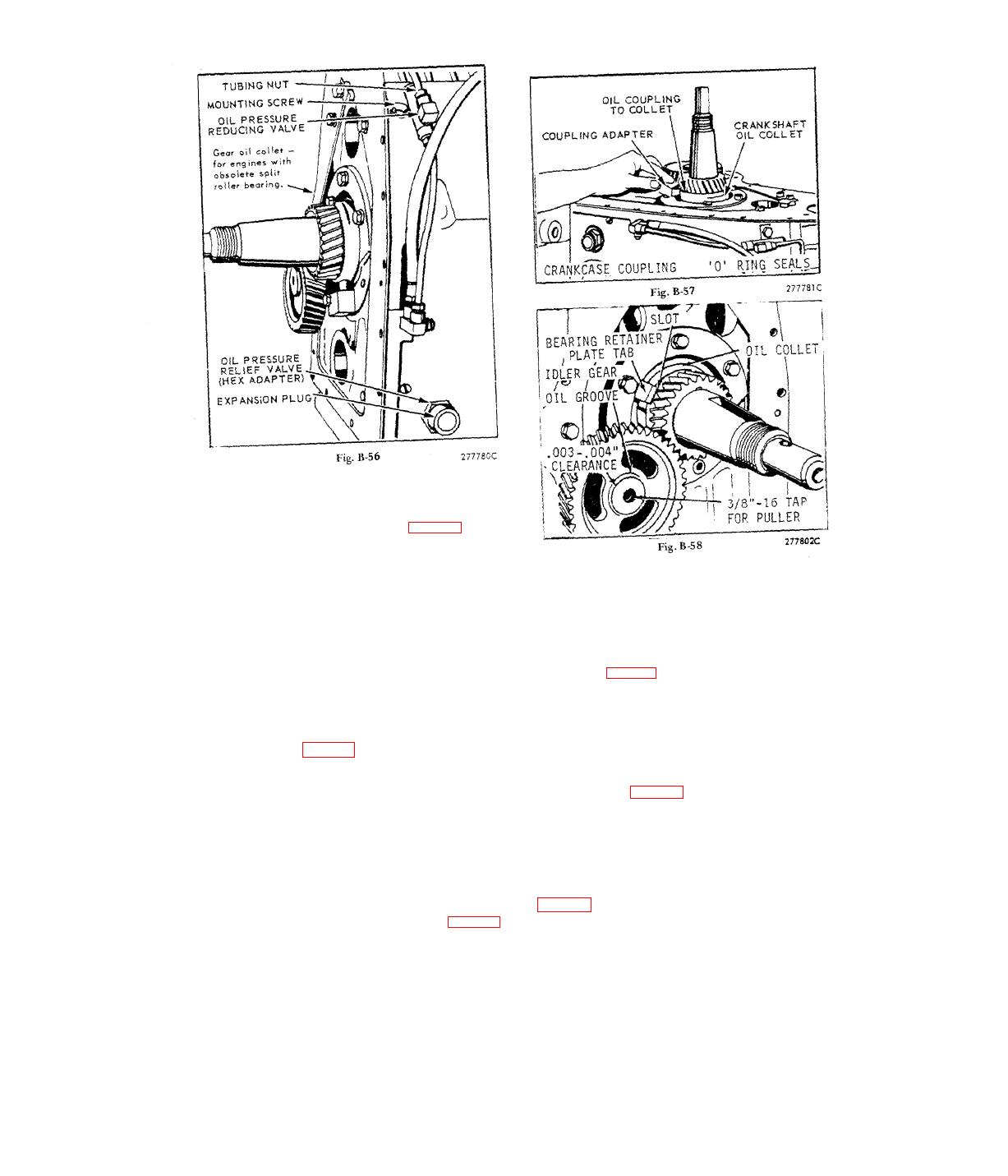
pansion plug after adjusting pressure as per "Oil
Pressure Adjustment" instructions at front of manual.
To replace the oil pressure reducing valve, loosen the
4 oil line nuts at the valve and at the fittings on top
Caution: It will be necessary to rotate the crank-
and side of crankcase. Remove valve mounting cap-
shaft so that counterweights clear the lugs in the
screw and lift valve away from crankcase. The oil
crankcase for the center main bearing, and the
lines will become unseated without being deformed.
lugs on the center bearing hanger will have to line
up with the clearance slots in the crankcase face.
In reassembly; hold valve in proper location but do
not mount. Place oil lines in position and engage
In reassembly; rotate crankshaft oil collet so that
tubing nuts 2 to 3 turns. Secure valve in place with
slot engages with tab on bearing retainer plate, as
capscrew and then tighten tubing nuts.
illustrated in. Fig. B-58. Mount main bearing plate, gas-
kets and shims, and torque capscrews to 32 foot
ASSEMBLY and DISASSEMBLY PROCEDURE
pounds. Check end play and add or remove gaskets
with obsolete
to give the necessary .002 to .004 inch movement,
ROLLER type CENTER MAIN BEARING
(Engines previous to serial No. 4904657)
Center main bearing (roller type) can be disassembled
in the following manner: Loosen and back out bear-
With reference to Fig, B-57, remove oil coupling from
ing hanger capscrews approximately 1/2 inch. Tap
crankshaft oil collet. Take out the adapter mounting
capscrew heads lightly and alternately with a hammer,
screw and slip oil coupling out of collet. In reassem-
as illustrated in Fig. B-59, to break cap away from
bly; use new `O' ring seals at both ends of the coupl-
hanger body. Do not pry cap and body apart. Remove
ing and on the shoulder extending into the crankcase.
capscrews and separate hanger and cap from bearing.
Lubricate 'O' rings for ease in assembly.
Take off retaining ring from outer bearing race and re-
Remove the center main bearing hanger to crankcase
move bearing halves and rollers from crankshaft.
mounting screws and spacers. Tip case back on en-
In reassembly; coat inside of bearing halves with a
gine supports and remove main bearing plate, gaskets
low melting point grease or petroleum jelly. Do not
and shims. Slip a length of pipe over the gear end of
use a standard lubricating grease. With reference to
the crankshaft and with the assistance of another per-
son, withdraw crankshaft with center bearing thru the
the bearing halves; assemble to crankshaft and clip
main bearing plate opening, as illustrated in Fig. B-55.
