
TM 9-3431-254-14&P
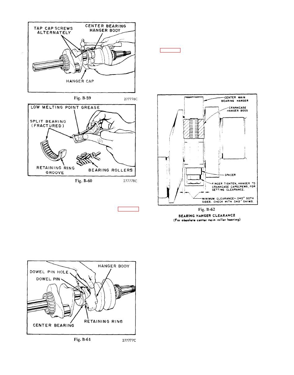
Secure bearing hanger to crankcase after crankshaft
end play is adjusted. Note: Beginning with engine
serial No. 4052826, the capscrews for mounting the
bearing hanger to crankcase were lengthened to 3
inches, and a spacer added under the screw heads,
see Fig. B-62. Thus all 4 screws for the center main
bearing hanger assembly are the same, minimizing
the possibility of improper assembly. Install hanger
capscrews, with spacers, finger tight and position
bearing hanger so that there is a minimum of .040
inch clearance between the sides of the bearing han-
ger and crankshaft cheeks. Tighten hanger to crank-
case capscrews, 60 foot pounds torque.
together with retaining ring. The ring must overlap
both mating edges of the bearing. Insert shouldered
dowel pin into either hole of the bearing race and
place the hanger body against the bearing so the
dowel slips into the dowel pin hole, see Fig. B-61.
Hold hanger body against bearing, place cap in posi-
tion and draw the capscrews finger tight until the 2
dowels are just entering holes. With a hand wrench,
alternately turn each screw to turns to evenly
draw cap tight to hanger body. Torque capscrews to
40 foot pounds, alternately in 3 stages; 15, 30 and
40 ft/lbs. A few squirts of oil in the hanger cap oil
hole will help to dissolve the bearing grease.
B-34
