
TM 9-3431-254-14&P
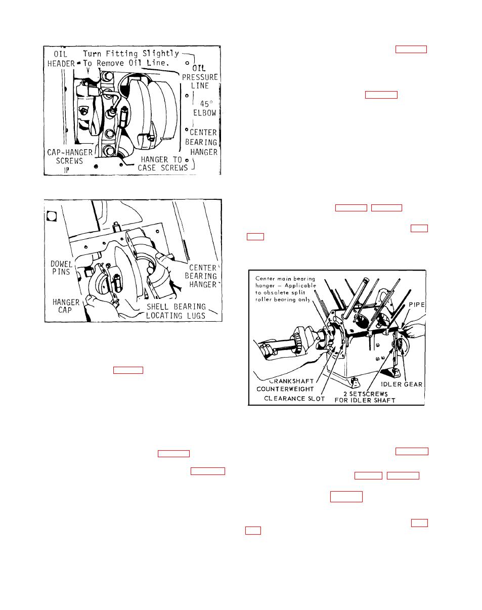
MAIN BEARING PLATE and CRANKSHAFT (Fig. B-55)
Remove main bearing plate, gaskets and shims from
take-off end of engine. Slip a length of pipe over the
gear end of the crankshaft and with the assistance of
another person, withdraw the shaft thru the main bear-
ing plate opening, as illustrated in Fig. B-55. Removal
of crankshaft with center hearing hanger assembled to
it applies only to the obsolete split roller bearing,
Caution: It will be necessary to rotate the crankshaft
so that counterweights clear the center main bearing
hanger lugs in crankcase.
In reassembly: Holes for the main bearing plate are
off-set for correct mounting. Assemble main bearing
plate, gaskets and shims, and torque cap screws to 32
foot pounds. Check end play and add or remove gas-
kets to give the necessary .002 to .004 inch move-
329160C
ment, with engine cold.
IDLER GEAR AND SHAFT (Fig. B-55, Fig. B-58)
A tapped hole in the side of the crankcase contains
2 setscrews for locking idler shaft in place. See Fig.
assemble shaft and gear from case by means of the
3/8"-16 tapped puller hole in end of idler shaft.
329161C
Do not pry cap and body apart. Separate and remove
hanger and cap with shell bearing from crankcase.
Check bearing and crankshaft journal for visible wear
proaches .005 inch, replace shell bearing with suit-
able undersize.
In reassembly: Clean thoroughly and apply a film of
oil to the bearing surfaces. Mount center main bearing
277806C
after crankshaft is assembled to crankcase and end
play is set.
In reassembly; be sure oil groove in shaft is facing
up. Drive shaft into crankcase with soft metal ham-
Dowel pins in cap are off-center so that when hanger
mer and maintain a .003 to .004 inch clearance be-
is mounted to cap, the locating lug on both bearing
tween idler gear and shoulder of shaft, see Fig. B-58.
halves, will be on the same side. See Fig. B-54. As-
Lock shaft in place with the 2 Allen set screws.
semble hanger so that 45 oil line elbow is facing to-
ward oil header side of case as illustrated in Fig.B-53.
OIL PRESSURE RELIEF VALVE (Fig. B-7, Fig. B-56)
Draw cap to hanger screws finger tight until the two
If it becomes necessary to remove the oil pressure
dowels are just entering holes. With a hand wrench,
relief valve, illustrated in Fig. B-56, either for cleaning
alternately turn each screw 1/2 to 3/4 turns to evenly
or replacement; first unscrew hex adapter and remove
pull cap tight to hanger body. Torque screws 32 to 35
expansion plug from adapter. With a 3/16 inch Allen
foot pounds.
wrench, remove outer adjustment lockscrew, see Fig.
Secure bearing hanger to crankcase after crankshaft
end play is set. Install capscrews and washers, torque
body and turn counter-clockwise for removal Do not
to 60 foot pounds.
use a pipe wrench or pliers to remove valve body.
Be sure oil fitting passages are clean. Connect oil
In reassembly; use new `O' ring in valve body and
line from header to bearing hanger.
apply sealer to threads of hex adapter. Assemble ex-
B-32
