TM 9-4110-255-14
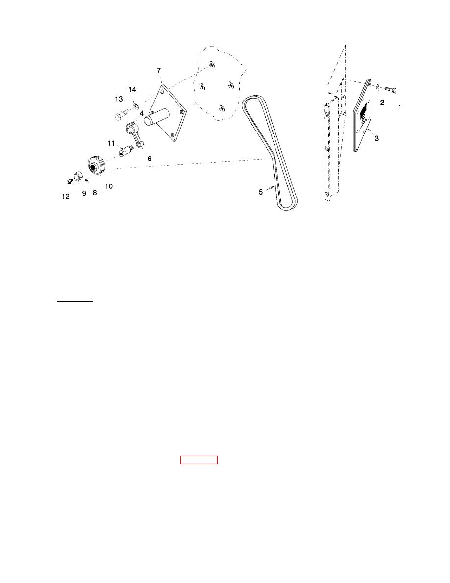
Figure 4-34. Idler Pulley
(5) If idler shaft (11) is damaged, remove it from idler arm (6). If lubrication fitting (12) is damaged remove
it from idler shaft.
(6) If idler bracket (7) is damaged, remove four bolts (13), lock washers (14), and idler bracket. Discard lock
washers.
b. Installation.
(1) If removed, install idler bracket (7), four new lock washers (14), and bolts (13.
)
(2) If removed, install idler shaft (11) onto idler arm (6) and lubrication fitting (12) into idler shaft.
(3) Slide idler pulley (10) onto idler shaft (11) then slide bushing (9) onto idler shaft and tighten set screw (8).
(4) Slide idler arm (6) onto idler bracket (7).
(5) Be sure idler pulley (10) is centered under fan V-belt (5). Push on idler pulley to set fan V-belt tension.
Belt tension is correct when 4 lb (2 kg) force is applied to the mid point of the belt and it deflects 0.38 in.
(1 cm). When the correct tension is reached, tighten bolt (4).
(6) Install access plate (3), eight new lock washers (2), and bolts (1).
NOTE
FOLLOW-ON MAINTENANCE:
Connect battery (para 4-35) and put unit back into service.
4-103


