
TM 9-4120-385-14
d.
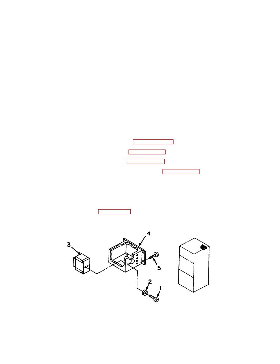
INSTALLATION.
1. Place switches (5 and 6) and sensing lines in unit. Excess sensing line should be
coiled and secured with 1inch tape.
2. Carefully feed sensing line through grommet.
3. Mount switches (5 and 6) inside enclosure (2) and secure with two screws (3) and
lockwashers (4).
Mount enclosure (2) and instruction plate with four screws (1).
4.
Connect the sensing line with flare nut to the refrigerant tubing.
5.
Connect electrical leads.
6.
Replace motor.
7.
Replace dehydrator. Refer to Paragraph 5-22.
8.
Perform leak test. Refer to Paragraph 5-3.
9.
10. Evacuate system. Refer to Paragraph 5-7.
11. Charge system with refrigerant. Refer to Paragraph 5-8.
12. Install top panel and secure with 11 screws and rain seal washers.
13. Install canvas cover and secure with 16 screws and rain seal washers.
5 - 1 9 . PRESSURE SWITCH
a . INSPECTION. See Figure 5-22.
