TM 9-4910-387-14-2
NOTE
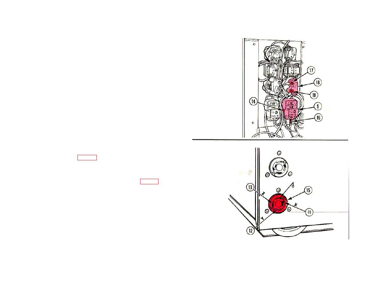
Relate X contact (11), Y contact (12), and Z contact (13)
with male connector plug in case female connector plug
is mounted differently than that illustrated.
4 Remove both leads. Connect one multimeter lead to contact (14) on
LUBE HEAT switch (5). Connect other lead to contact (11) on
female connector plug (15) where cable wire X is connected.
5 Remove both leads. Connect one multimeter lead to contact (16) on
LUBE HEAT switch (5). Connect other lead in sequence to contact
(13) on female connector plug (15) where cable wire Z is connected,
and to contact (17) on indicator light (18).
6 Remove both leads. Connect one multimeter lead to contact (19) on
indicator light (18). Connect the other lead to contact (12) on female
connector plug (15) where cable wire Y is connected.
7 Check for continuity. If continuity does not exist on any of the
checks performed in steps 4 thru 6 above, disassemble female
connector plug (15) (p 6-187) and check if wires are connected to
contacts.
a. Connect wires as necessary.
b. If wires are connected, replace the open wire (p 6-187).
6-59

