
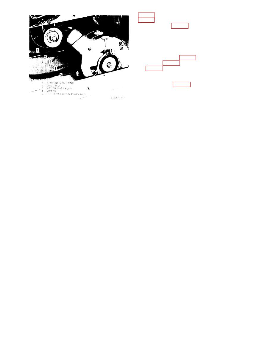
drive belt (2, fig. 11) from the motor and
variable drive unit pulleys.
c . I n s p e c t i o n . Inspect the be1t for
cracks, breaks, excessive stretch, and de-
terioration.
d. Installation and Adjustment. install
motor (4, fig. 11) and variable drive unit
(1, fig. 11). Slide the motor away from the
variable drive unit until the belt is snug but
not overly tight. Tighten the four hexagon
plain nuts (5, fig. 11) and check the belt
for proper tightness. The belt should have
about 1/2 -inch deflection when squeezed
half way between the motor pulley and the
variable drive unit pulley.
Figure 11. Drive belt, motor, and variable drive.
26
