the position of the drive reversing
observed during generator operation,
d(7) below.
switch, place the toggle switch on the
circuit breaker (fig. 11) in the "OFF"
d. Test Procedures.
position, as high voltage exists in the
(par. 99d).
surrounding area of this compart-
(1) The position of switches and controls
ment.
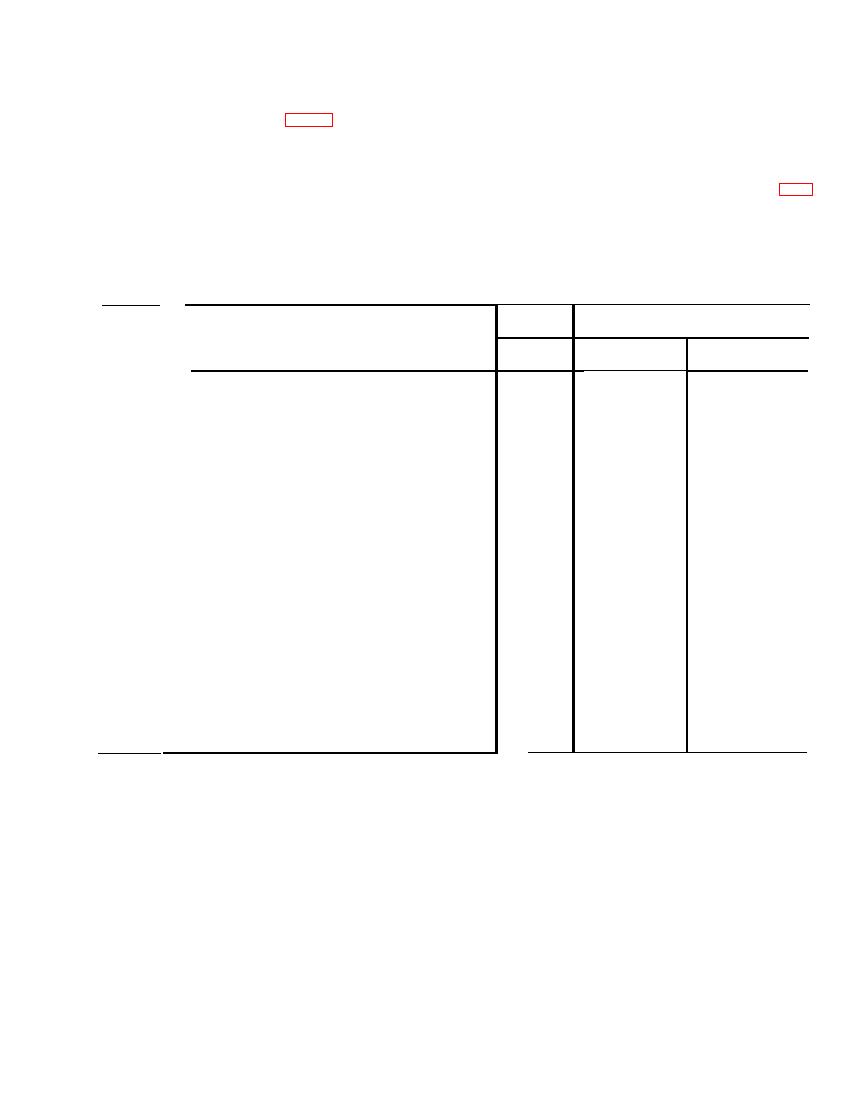
pertinent to this test are listed in table
(8) R e m o v e t h e w a t e r p r o o f i n s p e c t i o n
2 below. Place each of these items in
p l u g from the side of the generator
the position indicated in column 3a o f
the table before tests are started.
h o u s i n g , so that the brushes may be
(Delco-Remy or Auto-Lite 25-Ampere Generator)
(2)
(3)
(1)
Figure No. 32
Position
(b)
(a)
Key No.
After
Before
5
50A (X1)
500A (X10)
Load dc ammeter range selector switch . . . . . . . . . . . . . . . . . . .
.
6
5A (X1)
30A (X6)
Field dc ammeter range selector switch . . . . . . . . . .
.
7
9V
9V
Dc volts-millivolts range selector switch . . . . . .
.
8
50V (X5)
50V (X5)
Dc voltmeter range selector switch . . . . . . . . . .
.
9
RECT GEN
ANY
Dc voltmeter circuit selector switch . . . . . . . .
.
OFF
10
ON
Starter test load disconnect switch . . . . . . . . . . . . . . . . . . . . . . . . . . . .
.
11
DC
ANY
Field ammeter dc ac/dc switch . . . . . . . . . . . . .
.
12-A,
OFF
OFF
Load switches . . . . . . . . . . . . . . . . . . . . . . . . . . . . . . . . .
.
B and C
12-D
ON
OFF
0-25 0-12.5 load switch . . . . . . . . . . . . . . . . . .
13
Fully counter-
Fully counter-
Variable load 0-25 0-12.5 ampere rheostat . . . . . . . . . .
clockwise
clockwise
14
NEG GND
CENTER (OFF)
Polarity reversing switch . . . . . . . . . . . . . . . . .
15
INT GND
CENTER (OFF)
G e n e r a t o r field external-internal ground switch . . . . . . .
16
Fully counter-
Fully counter-
40-ohm field current rheostat . . . . . . . . . . .
clockwise
clockwise
17
RHEO
CENTER (OFF)
40-ohm 30 ampere maximum rheo-reg
switch .
.
.
.
.
18
OFF
OFF
250-ohm 5 ampere maximum switch .
....
.....
19
24V
24V
Battery circuit selector switch . . . . . . . . . . . . .
.........
..........
20
OFF
OFF
Battery
on-off
switch
.
.
.
.
.
.
.
.
.
.
.
.
21
S T O P (button
S T O P (button
Drive control . . . . . . . . . . . . . . . . . . . . . . . . . . .
..........
...........
depressed)
depressed)
22
one-quarter speed
one-quarter speed
Speed control handle . . . . . . . . . . . . . . . . . . . . . .
(turn counter-
(turn counter-
clockwise)
clockwise)
N o t e . The safety clip (21-B) must be off
(2) Place the battery on-off switch (20) in
t h e stop button (21-C) to perform the bat-
the "ON" position and turn the dc
t e r y check in (2) above. Do not push the
v o l t m e t e r circuit selector switch (9)
s t a r t button (21-A) as the varidrive assem-
to the "BAT VOLTS" position to de-
bly need not be running for this test.
t e r m i n e whether the battery voltage
(3) Place the battery on-off switch (20) in
o f the test stand is the same as the
t h e "OFF" position and turn the dc
voltage of the system under test. Cor-
v o l t m e t e r circuit selector switch (9)
rect voltage is 24 volts which will be
t o the "RECT GEN" position.
i n d i c a t e d on the dc voltmeter (4). If
(4) S t a r t t h e v a r i d r i v e a s s e m b l y , c ( 6 )
reading is less than 24 volts recharge
above, and turn the speed control
b a t t e r i e s (par. 98). It is also advisa-
handle (22) slowly clockwise until
ble to check the batteries with a hy-
2 , 5 0 0 rpm are indicated on the ta-
drometer for specific gravity (refer to
TM 9-6140-200-15).
c h o m e t e r indicator meter (3)
59

