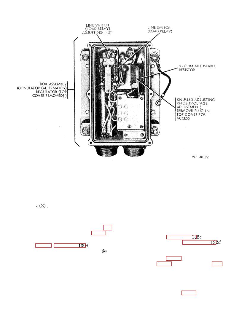
control and line switch (load relay) adjustment control.
checked and adjusted individually,
ally to make sure the hum does not
stop.
n a t o r ) regulator has been assembled.
(i) A f t e r a l l t e s t s a r e c o m p l e t e d i n
(2) P r e p a r a t i o n .
(3), and (4) above, remove
(a) C o n n e c t the assembled generator
all test leads and headset from the
(alternator) regulator (1) above,
test stand and assemble the genera-
a n d a generator (alternator), and
t o r (alternator) regulator by con-
rectifier of known serviceable con-
n e c t i n g the cover assembly, (fig.
d i t i o n on the test stand as pre-
55) on the box assembly (fig. 56).
and fol-
s c r i b e d in paragraph
( j ) Leave the switches and controls
in
l o w procedures in paragraph
remain
in
(1) through (6).
of
positions indicated in column
(b) R e m o v e t h e c a r b o n p i l e s u p p o r t
the table and continue with tests
in
cover (1, fig. 58), cover end plate
f below.
f. Operational Test and Adjustment of the
5 7 ) from the generator (alterna-
tor ) regulator.
l a t o r Assembled).
(3) Testing carbon pile flutter.
(1) General. The following tests are per-
Caution: Never allow voltage on
formed after the units of the genera-
the dc voltmeter (4, fig. 47) to exceed
t o r (alternator) regulator have been
32 volts during the following tests.

