
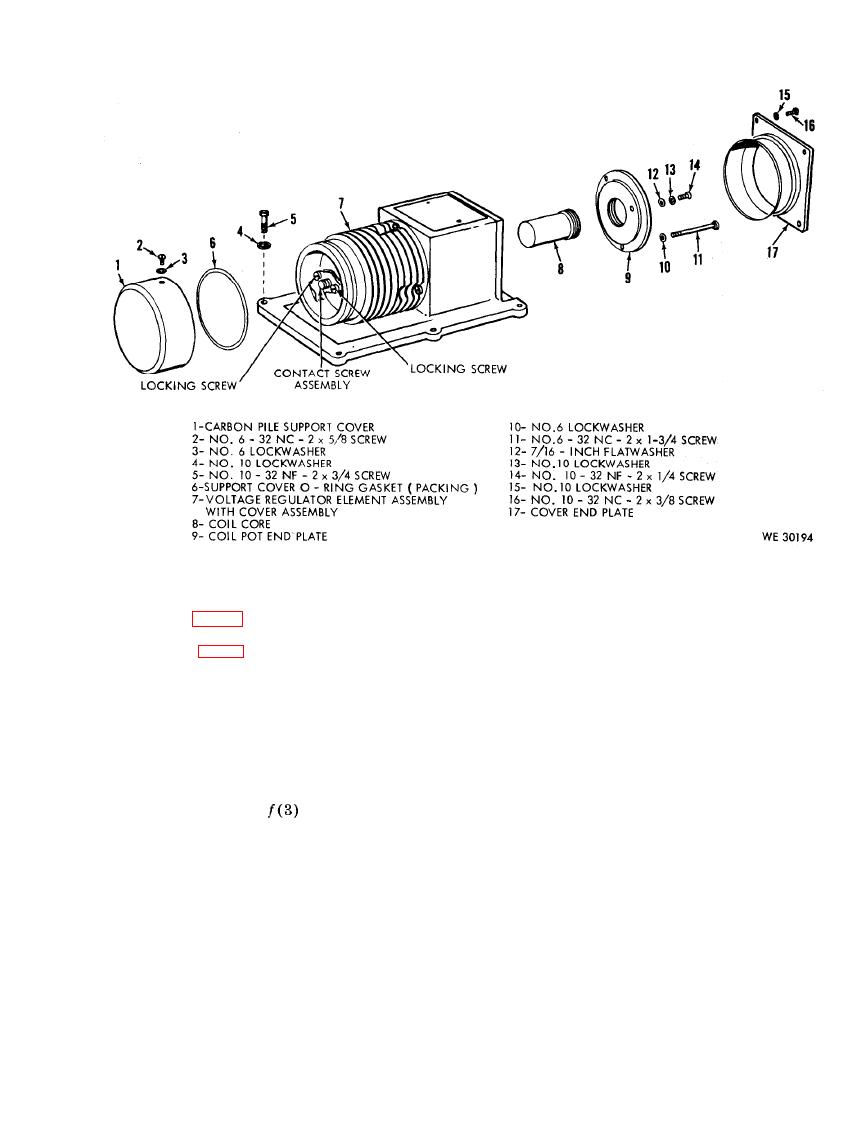
the above readings, the coil core (8,
crease the ampere load by placing
fig. 58) should be adjusted.
the 100-50 fixed load switch
Note. If the 5-ohm adjustable resistor
(17-A) in the "OFF" position and
placing the 50-25 fixed load switch
a spread of at least 5 volts, it should be
(17-B) to the "ON" position.
replaced.
(b) Increase the rpm of the varidrive
(g) Set the 5-ohm adjustable resistor
assembly by turning the speed con-
by adjusting as specified in ( f )
trol handle (24) counterclockwise
above until 28 volts is registered on
until 2000 rpm are indicated on the
the dc voltmeter (4). Apply 100
tachometer indicator meter (3).
ampere load by placing the 50-25
(c) Observe the dc voltmeter (4) and
fixed load switch (17-B) to "OFF"
if the voltage stays within the 27.4
(g) above, and then
position,
to 28 volts range, shock load the
place one of the 100-50 fixed load
r e g u l a t o r by placing the starter
switches (17-A) in the "ON" posi-
test load disconnect switch (15) to
tion and check to see that the volt-
the "ON" position then to "OFF"
age reading on the dc voltmeter
position several times. If the volt-
(4) remained within plus or minus
age still remains in the 27.4 to 28
o f the 28-volt setting indicated
volts range as will be indicated on
above.
the dc voltmeter (4), continue with
(5) Testing voltage adjustments at 2000
test in (6) below.
rpm.
(a) Place the battery on-off switch
(d) If the voltage reading on the dc
voltmeter (4) decreases more than
(22) in the "ON" position and de-
119
