
TM 9-4935-481-14-1
C2
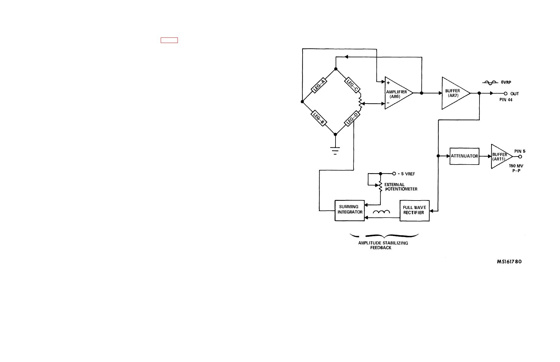
(e) The .5 Hz to 10 Hz 6V P-P signal is generated using the Wein bridge oscillator with automatic amplitude
stabilization. A block diagram of the Wein bridge oscillator is shown in fig. 3-31.
(f) Leg-A of the bridge consists of C23 in series with R18, R17A, R24, R25A, R26 and R27. Leg-B consists of
C22 in parallel with R28, R17B, R29, R25B, R30 and R31. Leg-C of the bridge consists of R19 and part of trim
potentiometer R20. Leg-D of the bridge consists of Q2 in parallel with R22, this combination in series with R21, and part of
trim potentiometer R20. The full wave rectifier consists of R32, R33, R34, AR8, C27, CR4, CR5, R35, R36, R37, R38, AR9
and C28. The summing integrator consists of R39, R40, R41, CR6, C30 and AR10.
(g) This system operates in the same manner as the high frequency oscillator described earlier. The frequency is
controlled by external switches shorting various resistors in Leg-A and Leg-B of the bridge. Energizing relay K1 disables
those switches and connects the resistors necessary for .5 Hz oscillations. If both relays K1 and K2 are energized the
frequency of oscillations changes to 5 Hz.
(h) The positive peak detector is composed of AR12, C37, CR8, C38, R47, C39, K6, R48, R49 and AR13. Its
output is brought out on P1-4. When the AR12 pin 1 input is grounded and the K6 relay is energized, the peak detector is
enabled when ground is removed from the input and +2.5 Vdc is applied in its place. As the capacitor C38 charges, the input
voltage reaches +2.5 Vdc. The output of the peak detector is now +2.5 Vdc and is verified at P1-4.
(i) The formula for the output voltage of the peak detector while the input is increasing in the positive direction is
(for A1 >>1, and A2 >>1):
Vout = [Vin + (Vd A1)] [1 - (1 A1) - (1 A1A2)]
where: Vd = Forward voltage drop across diode CR8
A1 = Open loop gain of amplifier AR12
A2 = Open loop gain of amplifier AR13
Because A1, and A2 are very large, the above formula can be simplified further to give
Vout = Vin + (Vd A1) where Vd A1 is the error voltage Vd is fairly constant and independent of Vin, therefore,
Vd/A1 is also fairly constant. Therefore, for small values of Vin, the percent error is larger than for large values of Vin.
(j) When the input voltage starts decreasing or the input is grounded, diode CR8 becomes reverse biased and
stops conducting while capacitor C38 holds the most positive (peak) voltage. Amplifier AR13 has a very high input
impedance (10
Figure 3-31. Block diagram of wein bridge oscillator
3-30.18
