spring center bolt and raise the vehicle frame until
rubber bushings into the shock absorber eyes and
the axle rests on the spring. Drop the spring clips
push them with large end of shock absorber up,
over the axle and through the spring clip plate.
onto the shock absorber shafts on the frame and
position the plate so that the shock absorber shaft
spring clip plate. Slip the washers over the shafts
end extends toward the inside of the shackle end of
and holding them against the rubber bushings,
the spring. Assemble the four spring clip lock-
install the cotter pin through the hole in the shaft.
washers and special nuts to the clips and tighten.
Bend back the cotter pin.
Section VIl. ELECTRICAL SYSTEM
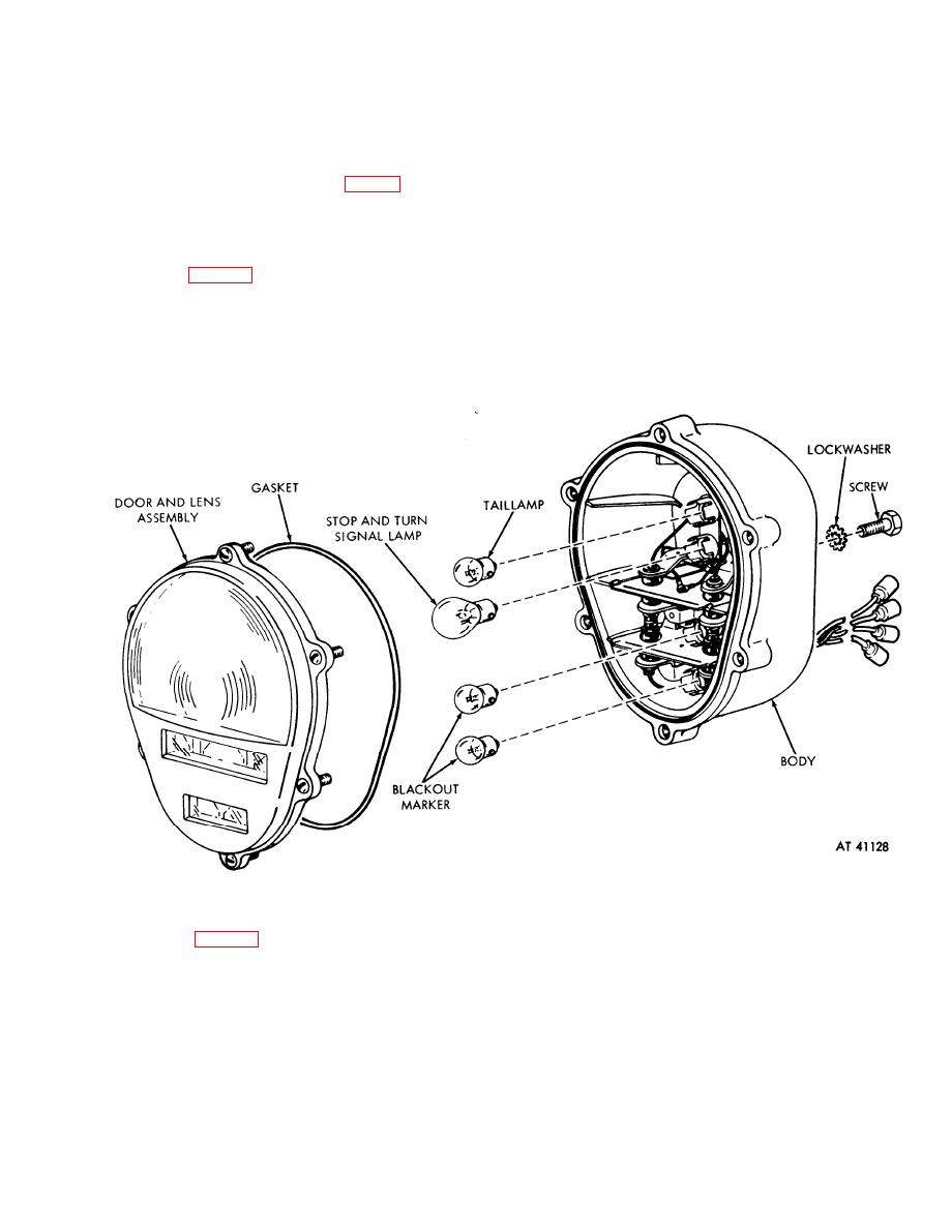
4-14. Lamps
direction until the bayonet-type fasteners on the
lamp base are free.
a. Removal. Remove the taillight door assembly
b. Installation. Insert the lamp into the bayonet-
and rubber gasket by loosening the six screws
type receptacle in the housing assembly and secure
holding the door to the housing. These screws have
it by pushing in and twisting in a clockwise
ring retainers to keep them from falling out of the
direction. Install the gasket and the door assembly
door when loosened. Remove the lamps by pushing
and tighten the six screws of the door assembly.
in and twisting them in a counterclockwise
Figure 4-7. Lamp replacement.
4-15. Taillight Assembly
the door is down. Place the split-type lockwashers
on the capscrews and insert the screws through the
bracket. Place the two tooth-type lockwashers on
a. Removal. Disconnect the taillight cables from
the screws so that they will be between the bracket
the wiring harness at the bell-type connectors (figs.
and light. Tighten the two screws into the back of
4-8 and 1-8). After removing the split rubber
the light. Push the taillight cables through the holes
grommet from the frame side member pull the leads
in the frame side members and connect them to the
through the hole one at a time. Remove the two
wiring harness by coupling the connectors (fig. 4-
capscrews, the two split-type lockwashers, and the
two tooth-type lockwashers holding the light to the
8). Connect the cables so that the numbered band
taillight bracket.
on the taillight cable corresponds to the band on the
b. Installation. Position the taillight against the
harness cable. Insert the rubber grommet into the
taillight bracket so that the lettering on the face of
hole in the frame side member.
4-9

