TM 9-2330-356-14
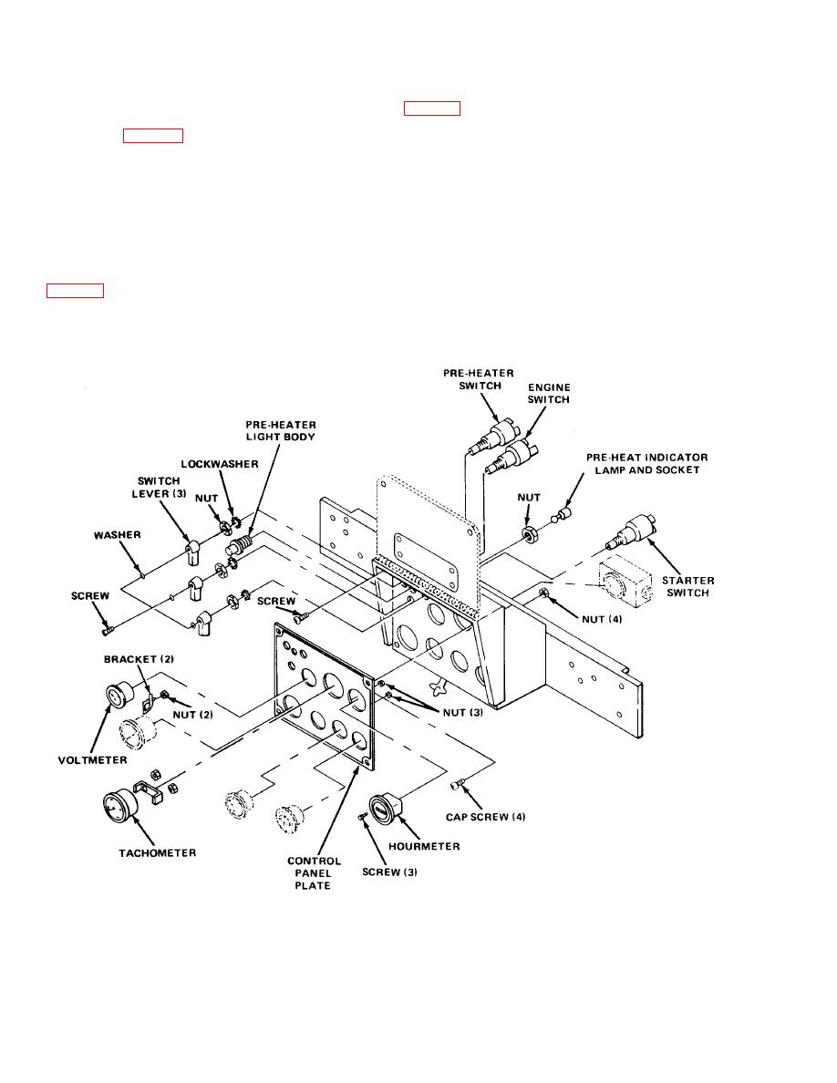
replacement. All switches and instruments must be
(b) Remove the screw and washer
replaced from the rear of the panel. Disconnect the
negative ground lead from the battery. Remove six round
head screws (fig. 4-39) holding control panel to frame.
(c) Remove the nut and lockwasher from
Swing control panel door down and hold open at 90 with
outside the panel, and remove switch.
20-inches of safety wire threaded through one hole in door
and corresponding hole in panel. Mark all leads before
NOTE
disconnecting. After replacing any component, close
panel door and replace six screws.
Aline locating tab on switch with locating hole
(1) Engine Switches (Preheater Starter and En-
in cover.
gine).
(a) Disconnect
the
electrical
leads
(d) Install new switch in reverse order of
steps (a) through (c).
TA223026


