
TM 9-2330-356-14
fail-safe unit to aline with brake lines. Tighten clamp
screw to 20-25 lb.-ft. Do not overtighten.
chamber unit to brake chamber and remove air chamber unit.
(8) Reconnect air hoses to brake chamber.
(5) Use a drift and hammer to loosen collet nut
(9) Manually release spring in fail-safe unit.
(6) Remove broke chamber and air chamber unit by
unscrewing the assembly from the plunger housing.
(7) At this time, the wedge assembly can be removed
for inspection or replacement (para 4-35).
Repair. Refer repair of broke chamber to direct support
e.
maintenance.
Installation of Brake Chamber and Air Chamber Unit.
f.
(1) Clean and install wedge assembly (if removed) into
plunger housing (para 4-35). Check position of wedge in plunger
housing to make certain wedge assembly is properly seated
(2) Make sure the spring in the air chamber unit is caged.
(3) Thread collet nut onto housing tube. Apply anon-
hardening seater (item 25, Appendix E) to the first three threads
of housing tube.
(4) With collet nut loose, turn the brake chamber into
plunger housing until it bottoms.
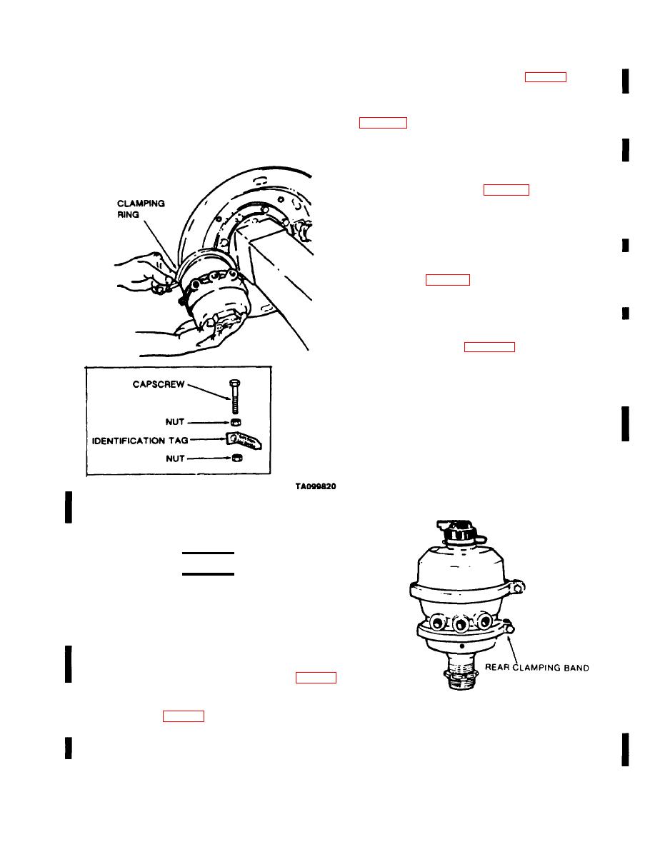
(5) Replace the air chamber unit on the brake chamber.
Clamp in place with clamp ring, using a nut and capscrew to
secure clamp.
(6) Aline connection ports with brake lines, if necessary,
by unscrewing brake chamber not more than one full turn.
M970 except M970 SN TC-0843, TC-0844, and
TC-103thruTC-178).
Repair of Fail-Safe Unit.
c.
WARNING
Do not attempt to repair brake chamber
fail-safe unit. It is dangerous because of high
spring compression. No repair Is authorized
for fail-safe unit.
Removal of Brake Chamber.
d.
(1) Cage the spring in the air chamber unit (para 2-4).
(2) Release air pressure by opening drain valves on
both air reservoirs (fig. 4-79).
(3) Tag and disconnect air lines from brake chamber
M969, and M970 except M970 SN TC-0843, TC-0844, and
and air chamber unit.
TC-103 thru TC-178).
4-91
Change 3
