TM9-2330-368-14 & P
Section III. OPERATOR MAINTENANCE PROCEDURES
Page
Page
Electrical System . . . . . . . . . . . . . . . . . . . . ...3-9
Wheels and Tires . . . . . . . . . . . . . . . . . . . . ...3-10
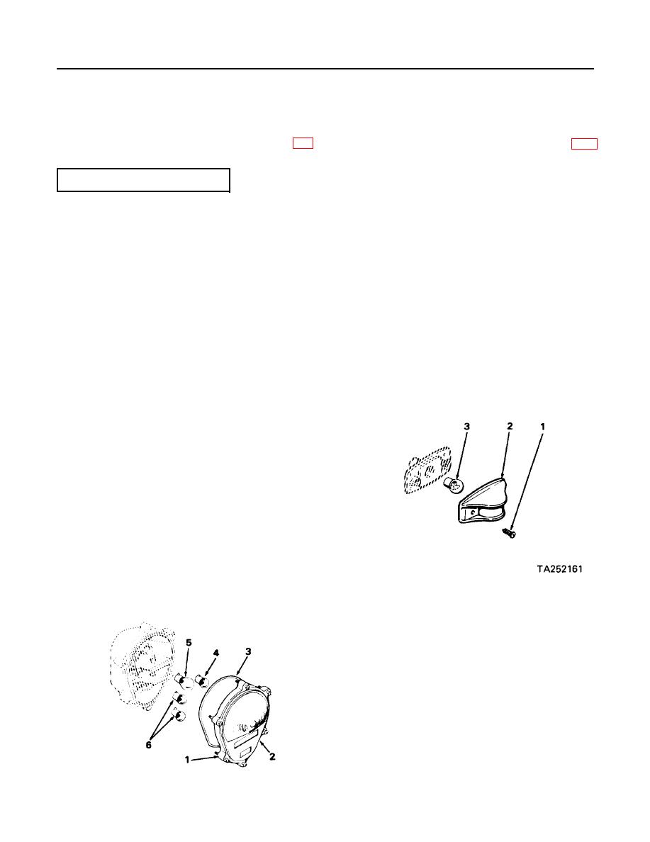
c. Clearance Marker Lights. Replace lamps as
3-5. ELECTRICAL SYSTEM
follows:
(1) Remove two screws (1) and light cover
(2).
a. General. Maintenance of the electrical sys-
(2) Remove lamp (3) by pressing in and ro-
tem at crew level is limited to replacement of the
tating lamp counterclockwise until it
lamps in the composite lights, marker lights and/or
releases; withdraw lamp from socket.
running lights.
(3) Insert new lamp in socket, press in and
b. Composite Lights. Replace lamps as fol-
rotate lamp clockwise until it locks in
lows:
place.
(1) Loosen six captive screws ( 1 ) and re-
(4) Position light cover (2) on body and in-
move lens assembly (2) with packing
stall two screws ( 1 ) to attach covers.
(3).
(2) Remove defective lamp (4, 5 or 6) by
pressing in and rotating lamp counter-
clockwise until it releases; withdraw
lamp from socket.
(3) Insert new lamp in socket, press in and
rotate lamp clockwise until it locks in
place.
NOTE
Be sure preformed packing (3) is
seated between light body and
lens assembly to seal the unit
properly.
(4) position lens assembly (2) on body and
tighten six captive screws (1 ).
3-9

