TM 9-2330-371-14&P
LEAD ASSEMBLY (RECEPTACLE) - CONTINUED
ACTION
ITEM
REMARKS
LOCATION
ASSEMBLY
10.
Four nonmetallic
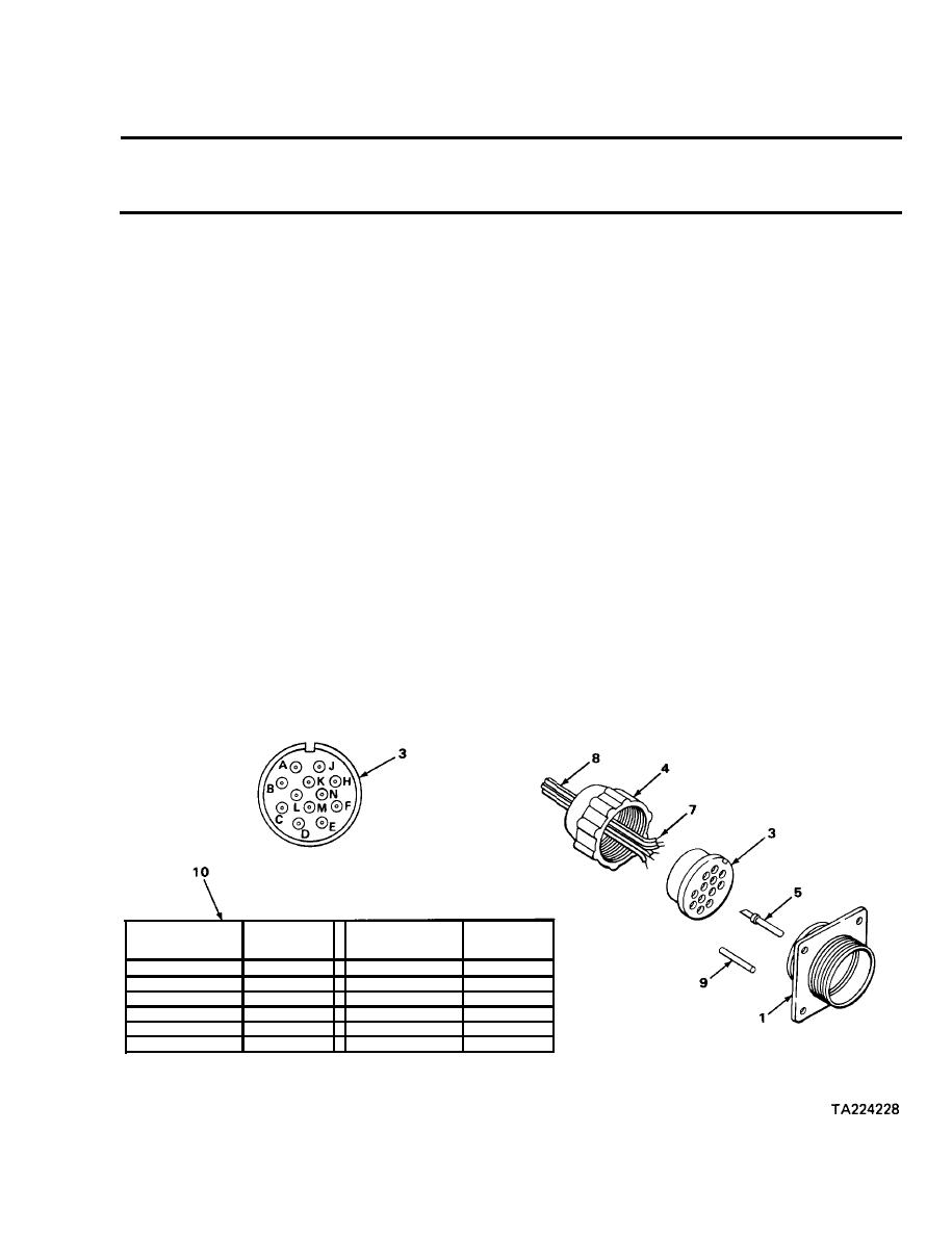
Push into grommet (3) terminal holes K, L,
Grommet (3)
rods (9)
M, and N.
Retaining nut (4)
Slide on wire (8) threads facing outward.
11.
12.
Eight wire ends (7)
Put into back of grommet (3) in the order
shown on chart (10) and pull through front
of grommet (3).
13.
Eight wire ends (7)
Using stripping pliers, strip insulation
equal to depth of solder well in
insert (5).
14.
Eight inserts (5)
a. Place solder well onto wire ends (7)
and solder using soldering tool.
b. Push solder wells into grommet (3)
until seated.
15.
Grommet (3)
Push into lead assembly (1).
16.
Retaining nut (4)
Screw onto lead assembly (1) and tighten.
CIRCUIT
TERMINAL
TERMINAL
CIRCUIT
DESIGNATION
NO.
DESIGNATION
NO.
H
490
24 AND 484
A
22 AND 460
J
22 AND 461
B
c
24 AND 483
K
Blank
L
Blank
90
D
M
Blank
21 AND 489
E
Blank
N
23
F

