
TM 9-2330-373-14 & P
4-17.
BRAKE ADJUSTMENT (cont)
NOTE
Try to laterally rock wheel, hub and brake drum assembly on axle spindle. If rocking condition exists;
adjust wheel bearings (para 4-30) before making brake adjustment.
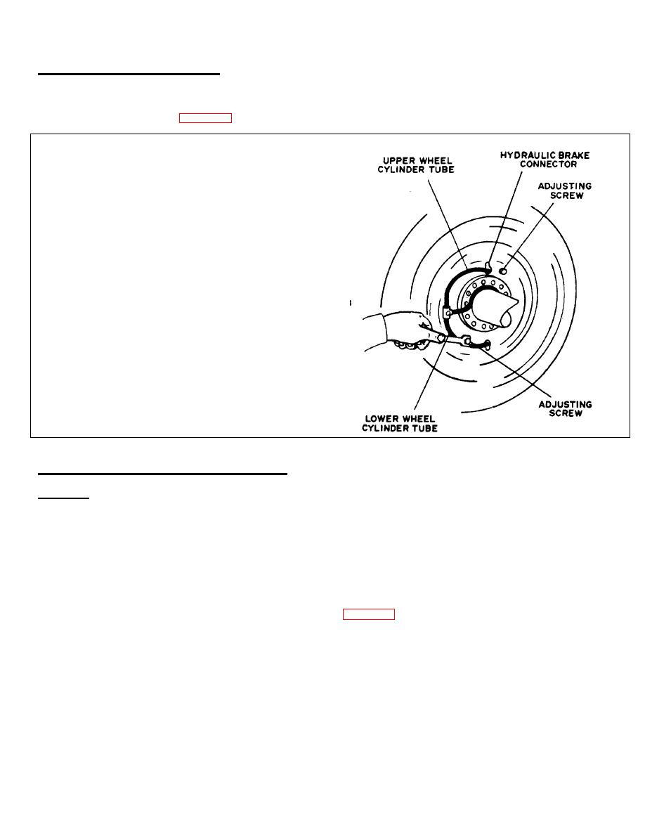
3. The upper brake shoe adjusting screw is located
at top rear face of brake backing plate. Turn
screw clockwise until brakes drag slightly when
wheel or drum is turned by hand.
4. Back off screw just enough to allow drum to
rotate freely.
5. The bottom brake shoe adjusting screw is
located at bottom rear face of backing plate.
Turn this screw clockwise and repeat pro-
cedures of steps 3 and 4 above.
6. Repeat this procedure on all other wheels.
Make both adjustments at each wheel as
uniform as possible.
Shoe adjusting bolt and
spring assemblies lock brakes in set position.
7. Close drain cock, lower tires to ground, and
remove jacks.
14-18. BLEEDING HYDRAULIC BRAKE SYSTEM I
GENERAL
Proper operation of brake system requires a solid column of fluid (without air bubbles).
Bleed the system to expel any air which may have entered. Need for bleeding is generally indicated by soft brake action.
Bleeding can be done manually or with pressure feed filler. Towing vehicle must be coupled to semitrailer for manual
bleeding operation.
Front axle wheels and rear axle wheels should be bled individually and each
applicable master cylinder used (see hydraulic system schematic, page 4-75).
TA 314772
4 -51
