
TM 9-2330-373-14 & P
4-20.
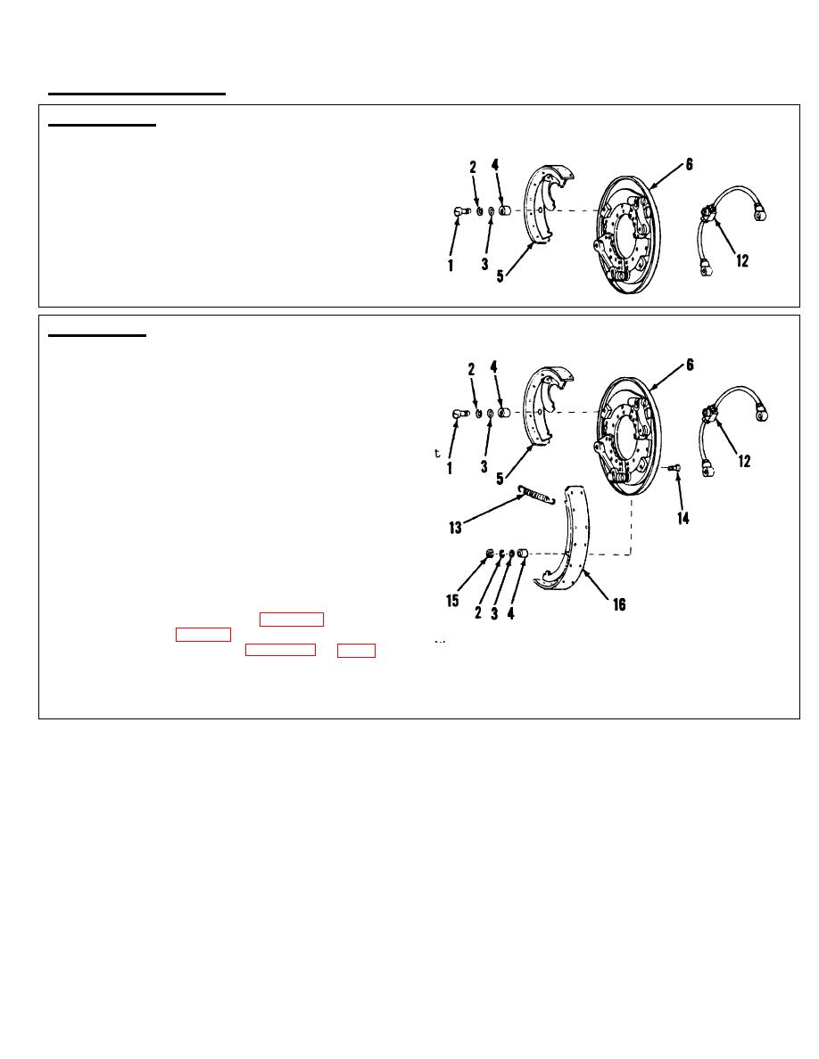
BRAKE SHOE (cont)
REMOVAL (cont)
6.
At the rear brake shoe (5), remove cap screw
(1), lock washer (2), guide screw washer (3), and sleeve
spacer (4) which secure brake shoe and wheel cylinder
tube assembly (12) in position.
7.
Disengage the brake shoe from wheel cylinder
piston rod and anchor supports.
INSTALLATION
1.
Position either brake shoe against brake backing
plate and slide into place in anchor supports and
wheel cylinder piston rod. Install other brake
shoe in same manner.
2.
Assemble guide bolt sleeve spacer (4), guide
screw washer (3), and lock washer (2) on cap
screw (1).
3.
Aline tube connection fitting, part of tube
assembly (12), with guide hole at the rear of
backing plate.
4.
Install assembled guide screw through slot in
brake shoe (5) and into fitting at rear of backing
plate (6). Tighten guide screw.
5.
Insert guide bolt (14) from rear of backing plate
(6) through slot in shoe. Assemble guide bolt
sleeve spacer (4), guide bolt washer (3), washer
(2), and nut (15) on guide bolt (14).
Tighten
nut.
6.
Install hub and brake drum (para 4-30).
7.
Install wheel (para 3-7).
8.
Bleed and adjust brakes (paras 4-18 and 4-17).
TA 314777
4-56
