
TM 9-2330-386-14&P
445 LANDING GEAR (CONT) .
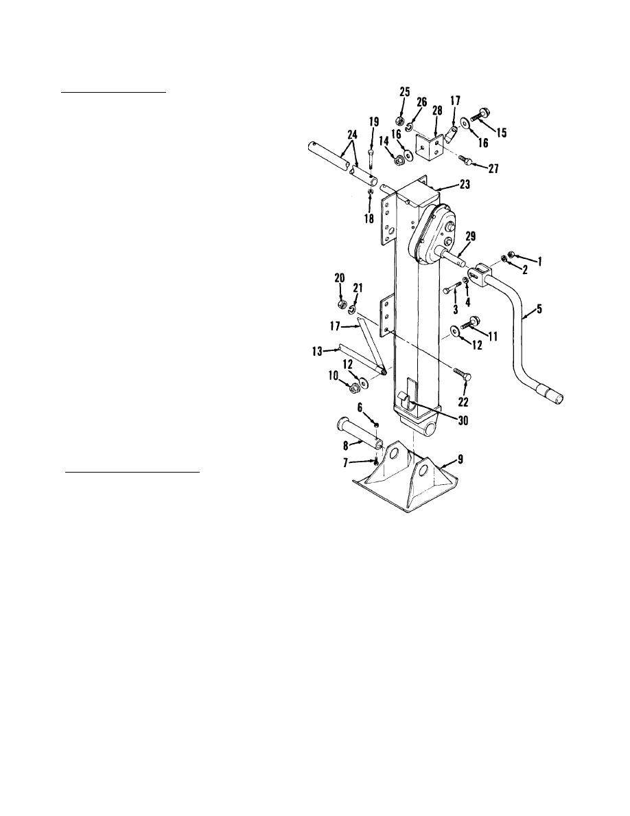
c. Landing Leg Removal.
NOTE
This procedure is typical
for both landing legs.
R e m o v e two lock nuts (10) , cap-
(1)
screws (11), four washers (12),
and brace (13).
R e m o v e two lock nuts (14), cap-
(2)
screws (15), four washers (16),
and two braces (17).
R e m o v e lock nut (18) and capscrew
(3)
(19) from drive shaft (24).
W e d g e blocks under landing leg
(4)
(23) to support weight.
R e m o v e 14 nuts (20), lock washers
(5)
(21), and capscrews (22) from
landing leg (23) plates.
W i t h your helper, remove landing
(6)
leg (23).
R e m o v e four nuts (25), lock
(7)
washers (26), capscrews (27),
and two brackets (28).
d. Landing Leg Installation.
(1) Install two brackets (28), four
capscrews (27), lock washers (26),
and nuts (25). Torque nuts (25) to
80 lb-ft.
NOTE
If drive shaft (24) is installed, guide landing leg (23)
shaft into drive shaft (24).
(2) With your helper, position landing leg (23) against semitrailer frame and
aline holes.
(3) Wedge blocks under landing leg (23) to support weight.
( 4 ) I n s t a l l 1 4 c a p s c r e w s ( 2 2 ) , lock washers (21), and nuts (20). Torque
capscrews (22) to 150 lb-ft.
NOTE
Be sure the landing legs are extended the same distance.
4-86
