
TM 9-2330-388-14
CHAPTER 7
REPAIR OF ENGINE ASSEMBLY
Section I. DESCRIPTION
b.
The terms right, left, front, and rear used in this
7-1.
Scope
technical manual, with reference to the engine and its
components, are determined as viewed from the front or
a.
This chapter contains instructions for direct and
flywheel end of engine.
general support maintenance of the engine and related
parts which are beyond the scope of using organization.
Section II. DIRECT AND GENERAL SUPPORT MAINTENANCE OPERATIONS FOR M1098 ENGINE
mm washer-type shims on end of injector or resting on
7-2.
Injector Removal, Test and Installation
plane in housing.
a.
Removal
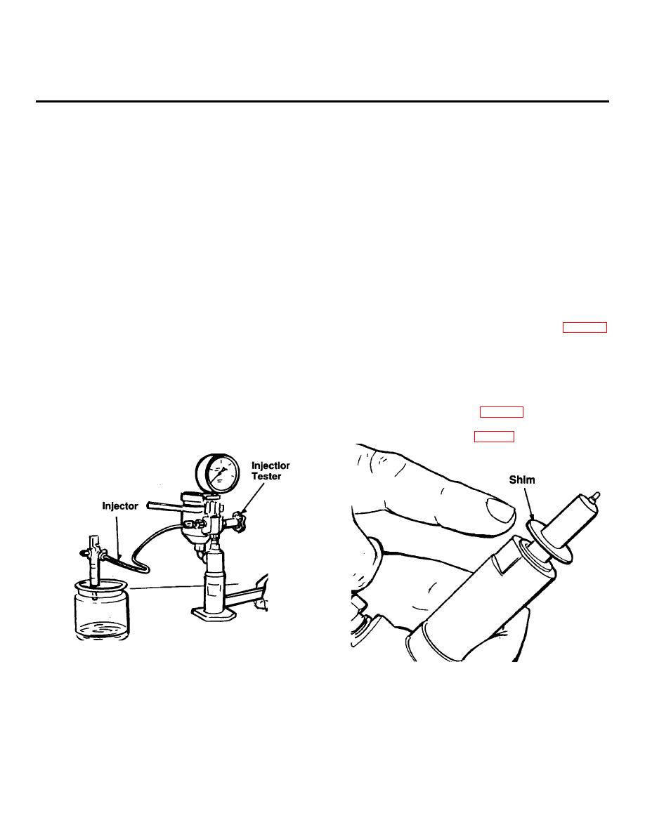
1.
Test fuel injector for breakaway pressure and
pattern using Injection Tester 49100-255-641. Use
1.
Disconnect upper red
alternator-to-voltage
Adapter G-3.
regulator wire at voltage regulator.
Test injector following tester instructions, fig. 7-1.
2.
Disconnect
negative,
then
positive
battery
Breakaway setting is approximately 2,300 psi.
cables.
c.
Installation
3.
Remove fuel pump-to-injector high pressure line
injector by disconnecting fitting.
1.
Install injector in cylinder head, make sure the
correct number of shims are installed between the
4.
Remove one bolt that holds low-pressure injector
injector and cylinder head, fig. 7-2. The number of
line to injector and position line out of the way.
shims needed are shown by the number of points
marked in the cylinder head, fig. 7-3.
b.
Test
Figure 7-1. Injector Testing
Figure 7-2. Placing Shims on Injector
5.
Remove two nuts that secure injector to cylinder
head and remove injector. End of injector will have .5
7-1
