
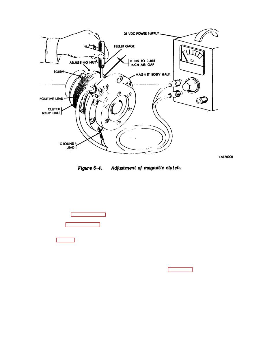
Figure 6-4. Adjustment of magnetic clutch.
Section III. REPAIR OF HYDRAULIC PUMP ASSEMBLY
6-12.
6-13.
6-14.
Disassembly (Fig 6-5).
d. Remove front cover (11) and preformed packing
a. To insure correct reassembly, use a center
(5).
punch and mark both sides of the pump housing and the
two covers so that they can be assembled in the original
e. Brush wear plate (6) with blue layout dye (MIL-
position.
LI83795) (15, appendix F) to insure proper assembly.
Remove two bearings (4), wear plate (6), and gasket (9).
b. Turn hydraulic pump assembly end cover (15)
down.
f. Brush tops of two gears (8 and 13) with blue
layout dye to insure proper assembly.
c. Remove four screws (10) and nuts (16) which
attach covers (11 and 15) to pump housing (12).
6-5
