
TM
9-3431-254-14&P
313024C
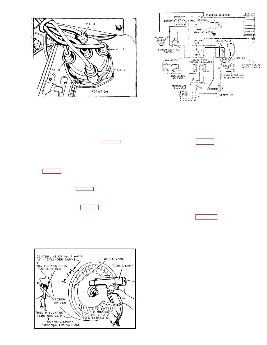
Fig. B-13 DELCO-REMY DISTRIBUTOR MOUNTING
Fig. B-15
DISTRIBUTOR IGNITION - WIRING DIAGRAM
If care is exercised in the preceding instructions, the
spark timing should be accurate enough for satis-
Chalk or paint the end of the `X' marked vane on the
factory starting, however, checking spark advance
flywheel, white. Then with the engine operating at
with a neon lamp, as described in " N e o n L a m p T i m -
2000 R.P.M. o r o v e r , allow the flash from the neon
ing" is necessary.
lamp to illuminate the whitened vane. At the time of
The No. 1 terminal tower for the D e l c o - R e m y distribu-
the flash, the leading edge of the vane should line up
with the r u n n i n g s p a r k a d v a n c e t i m i n g h o l e on the
tor is located in an approximate 2 o'clock position on
the distributor cap, as illustrated in Fig. B-13, and in
f l y w h e e l s h r o u d , see Fig B - 1 4 . If it does not, the dis-
tributor clamp screw should be loosened and the dis-
an approximate 1 o'clock location for the P r e s t o l i t e
d i s t r i b u t o r . T h e t e r m i n a l s e q u e n c e i s 1 - 3 - 4 - 2 in a
tributor body turned slightly clockwise or counter-
clockwise, as required, until the white flywheel vane
counter-clockwise direction. Mount ignition cables to
spark plugs of like numbers, with the center terminal
matches up with the advance timing hole. Be sure
tower connected to the ignition coil. S e e W i r i n g D i a -
clamp screw is then carefully tightened.
gram, Fig B-15. The cylinder shroud covers are marked
If the engine is running below 2000 R.P.M. when tim-
for spark plug identification.
ing, the automatic advance in the distributor will not
be in the "full advance position" and thus the timing
would not be accurate.
NEON LAMP TIMING (Fig. B - 1 4 )
The engine should be timed to the 23 advanced posi-
DISTRIBUTOR MAINTENANCE
tion at not less than 2000 R.P.M. C h e c k t i m i n g w i t h
a neon lamp as shown in Fig. B-14 insert a small screw
T h e n o r m a l b r e a k e r p o i n t g a p i s 0.020 inch at full
driver into the No. 1 terminal tower on the distributor
separation and can be adjusted in the following man-
cap, making contact with the spark plug wire terminal.
ner, with reference to Fig's B-11 or B-12; Turn engine
over by means of the starting crank until the distri-
Connect the red terminal clip, from a conventional
butor breaker arm rubbing block is on a high point of
type timing lamp, to the metal portion of the screw
the cam. Loosen the stationary contact l o c k s c r e w
driver. One of the other two timing lamp wires is con-
very slightly and insert a feeler gauge between the
nected to the battery, and the other to ground.
points. By means of a screw driver inserted into the
adjusting slot of the D e l c o - R e m y distributor or by the
a d j u s t i n g s c r e w of the P e s t o l i t e distributor, open or
close points as required until a slight drag is felt
when sliding feeler gauge between the points. Tighten
lockscrew and recheck gap.
Every 50 hours of operation, the oiler on the side of
the Pestolite distributor base should have 3 to 5
drops of medium engine oil added. The old style
D e l c o - R e m y distributor has a built-in oil reservoir.
Every 200 hours of operation, remove oil plug in base
and refill with No. 20W oil. Seal plug in reassembly.
The new style Delco-Remy distributor does not have
an external oil plug, since it is self-lubricated by oil
in the accessory drive housing.
Every 100 hours, apply 3 to 5 drops of light engine
oil (10W), to the felt in the top of the cam sleeve,
Fig. B-14
277786C
and 1 or 2 drops to the breaker arm pivot.
