TM 9-3431-254-14&P
Every 200 hours, add a small amount of high melting
point grease to breaker arm rubbing block, or oil the
cam wick.
excessive lubrication. oil that may get on the
Avoid
contact points will cause them to burn.
GENERATOR
A 12
equipment, unless otherwise s;pecified. The generator
is manufactured by either the Delco-Remy Company
or Prestolite Company.
Every 50 hours of operation, add 3 to 5 drops of
medium engine oil into the oil cap at both ends of
the generator.
ELECTRICAL
WIRING
CIRCUITS
Beginning with engine serial No. 3979807, the stan-
dard wiring circuits for all electrical equipment is
for n e g a t i v e g r o u n d polarity, instead of the pre-
viously furnished positive ground.
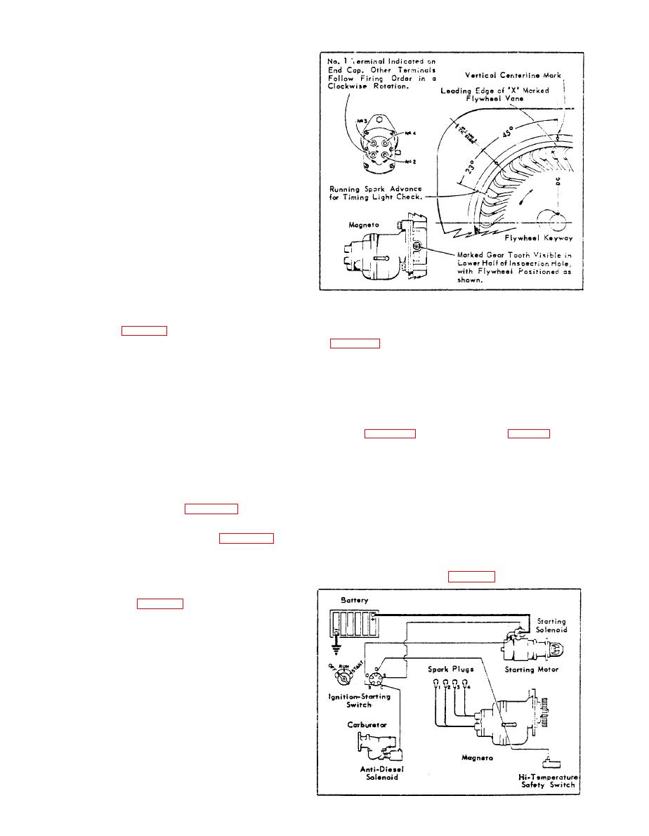
MAGNETO TIMING DIAGRAM
The wiring diagram, Fig. B-15, illustrates a negative
hole in gear cover. See Magneto Timing Diagram,
ground circuit. To wire equipment that has a posi-
Fig. B-16. Securely tighten nut and capscrew for
tive ground polarity; reverse terminal connections at
mounting magneto.
The No. 1 terminal is identified on the magneto cap.
The terrninals follow the proper firing order of 1-3-4-2
positive ground generator and regulator in
in a clockwise direction viewing the cap end. The
Do not use
a negative ground circuit, or vice versa. Polarity
leads from the magneto should be connected to spark
does not affect starting motor, coil and distributor.
plugs of corresponding numbers, see Firing Order
MAGNETO
TIMING
When magneto is properly timed the impulse coupling
For engines furnished with magneto ignition in place
will snap when the `DC' - `X' marked vane of the fly-
of distributor ignition, timing is accomplished in the
wheel lines up with the mark on flywheel, which in-
following manner:
dicates the centerline of the No. 1 and 3 cylinders.
1. Expose timing marks on flywheel and shroud. Refer
This can be checked by turning crankshaft over slow-
ly by hand. The impulse will also snap every 180 of
flywheel rotation thereafter.
Position No. 1 piston on compression stroke, as
2.
The running spark advance is 23. To check timing
with a neon light, the advance is indicated by a hole
With No. 1 piston on compression stroke turn en-
3.
on the flywheel shroud, 23 before centerline of t h e
gine over past top dead center, until the leading
edge of the `X' marked vane on the flywheel is in
l i n e with the vertical centerline mark on the
this position (flywheel keyway will be on top).
Remove inspection hole plug, located in gear cover
4.
at magneto mounting flange.
5. Assuming the magneto is removed from the engine;
set magneto for spark discharge to the No. 1 ter-
minal. This is accomplished by use of a short
stiff length of wire placed into the No. 1 terminal
socket and bent to within 1/8 inch of the magneto
frame. Then turn the magneto gear in a clockwise
rotation, tripping the impulse coupling, until a
spark is observed between the wire and frame. Re-
tain gear in this position.
6. Place gasket on flange and mount magneto to en-
gine, meshing the gears so that when magneto is
assembled, the gear tooth marked with an `X' will
be visible through the lower half of the inspection
MAGNETO
IGNITION
-
WIRING
DIAGRAM
B-16


