
TM
9-3431-254-14&P
The shifter shaft should be lubricated periodically
if external oil fittings are provided for this purpose.
The reduction unit is operated in oil and the gear
case oil level must be maintained to the oil saber
g a u g e mark or plug opening, see Fig. B-27. In Twin
Disc units, h i g h g r a d e t r a n s m i s s i o n o i l S . A . E . No.
9 0 to No. 110 Viscosity must be used. For Rockford
u n i t s , use No. 30 S.A.E. crankcase oil. Change oil
every 2000 hours of service, while unit is warm.
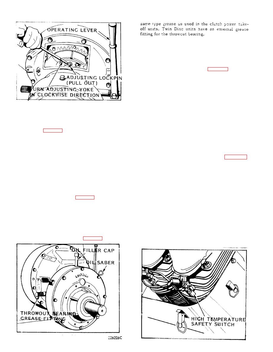
I f clutch slips, heats, or operating lever jumps our,
104578C
t h e clutch, must be adjusted. Release clutch operat-
TWIN DISC CLUTCH ADJUSTMENT
ing lever and remove hand hole plate. The clutchu in
t h e clutch reduction units is the same as is used in
F o r the Twin Disc clutch, pull adjusting lockpin out
the clutch power take-off units. Refer to "Clutch Ad-
a n d insert a piece of 1/16" diameter wire into the
j u s t m e n t " paragraph for adjustment of the clutch in
hole on the side of the lockpin to keep pin in outer
the Twin Disc and Rockford clutch reduction in units.
position, See Fig. B-26. Turn the adjusting yoke in a
A new clutch generally r e q u i r e s s e v e r a l a d j u s t m e n t s
clockwise direction as shown, or wedge a screw
until the friction surfaces are worn in.
d r i v e r into the adjusting yoke and against the side
o f the inspection hole opening to keep yoke from
turning, and then turn the take-off shaft counter-
clockwise. Tighten yoke enough so that the operating
HIGH TEMPERATURE SAFETY SWITCH (Fig. B-28)
l e v e r requires a distinct pressure to engage. Remove
The high temperature safety switch is mounted on the
wire from lockpin and trim adjusting yoke slightly, to
c y l i n d e r head near the No. 4 spark plug. This safety
allow lockpin to snap into hole in floating plate.
s w i t c h will automatically stop the engine when head
A new clutch requires several adjustments until fric-
t e m p e r a t u r e s become critically high.
t i o n surfaces are worn in. Do not let a new clutch
s l i p , this may ruin the friction surfaces.
If an extreme cylinder head temperature causes the
s w i t c h to automatically short out the ignition system
CLUTCH REDUCTION UNIT (Fig. B-27)
and stop the engine, a waiting period of about 5 mi-
The clutch in the clutch reduction units is of the dry
n u t e s will be required before the switch has cooled
disc type, the same as is used in the power take-off
o f f sufficiently to allow the engine to be resatrted.
u n i t s . Therefore, no oil should be put in the clutch
A n overheated engine will score the cylinder walls,
housing.
burn out connecting rod and crankshaft bearings, also
warp pistons and valves. The cause of the over-
The throwout bearing should be lubricated once a day
heating condition will have to be remedied before the
before starting. Add grease to fitting thru opening on
e n g i n e is restarted. See Engine Overheats paragraph
side of housing, as illustrated in Fig. B-27, using the
in Troubles. Causes and Remedies section.
ROCKFORD CLUTCH REDUCTION UNIT
Fig. B-28
B-20
