TM 9-3431-254-14&P
bearing greased every day before starting. Use
general (lube) grease, MIL-L-10924.
Rockford PTA-4856 units have a sealed pilot bearing
and require no external lubrication. Obsolete
PTA-4819 units have a pilot bearing grease fitting at
the end of the drive shaft and are lubricated same as
the linkage slightly and will enable the carburetor
the housing bearing.
throttle lever to bounce back from the stop pin rather
CLUTCH ADJUSTMENT (Fig. B-25 or Fig. B-26)
than jam against the pin, when a load is suddenly ap-
plied to an idling engine. This will eliminate exces-
If the clutch begins to slip it should be readjusted,
sive wear on the threads in the carburetor throttle
otherwise it will become overheated and damaged.
swivel block.
First, remove the clutch inspection plate and release
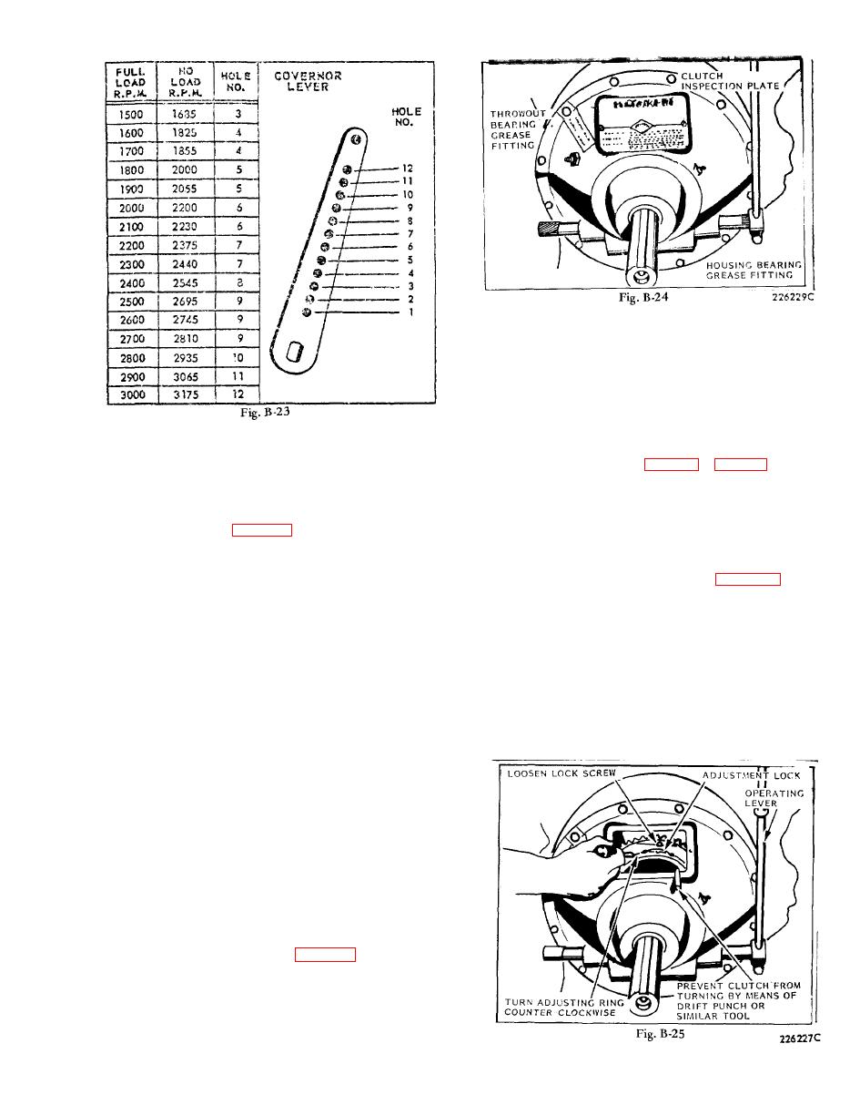
The governor lever, Fig. B-23, is furnished with 12
the clutch operating lever. For the Rockford clutch,
holes for attaching the governor spring. It is very im-
turn engine over by means of the hand crank until the
portant that the spring is hooked into the proper hole
clutch adjustment lock is visible thru the inspection
to suit the speed at which the engine is to be opera-
opening in the clutch housing, see Fig. B-25. The
ted. The Governor Lever Chart shows the full load
clutch must be held stationary, either by means of a
and no load speeds of the engine and the hole cor-
drift punch wedged in place as shown, or by some
responding thereto, for either a fixed speed, a vari-
convenient method of keeping the take-off shaft from
able speed or two speed (over-center idle control)
turning. Loosen screw holding the adjustment lock in
governor. Note that the full load speed is less than
place. Insert a screw driver in one of the notches and
the no load speed and this must be taken into consi-
turn the adjusting ring in a counter-clockwise direc-
deration when readjusting the governor. As an ex-
tion, one notch at a time, until a very firm pressure is
ample; if the engine is to be operated at 2000 revolu-
required to engage the clutch with the operating lever.
tions per minute under load, the spring should be
Tighten adjusting lock screw and mount inspection
hooked into the 6th hole in the governor lever and the
cover.
spring tension adjusted, by means of the adjusting
screw, to run 2200 R.P.M. under no load. The speed
at full load will then be approximately 2000 revolu-
tions per minute.
A tachometer or revolution counter should be used
against the crankshaft to check speed while adjust-
ing the governor spring tension. Tightening the ad-
justing screw locknut will give higher speeds, while
loosening the locknut will lower the spring tension
and reduce the R.P.M.
CLUTCH AND REDUCTION UNITS
The clutch available on this engine is of the dry disc
type. No oil should be put into the clutch housing,
but grease gun fittings are provided for periodic bear-
ing lubrication. The housing bearing should be greased
every fifty hours of operation and the clutch throwout
ROCKFORD CLUTCH ADJUSTMENT
B-19


