
TM 9-4120-370-14
TO 35E9-229-1
4-7.
REMOTE MOUNTING OF CONTROL PANEL - Continued
d. Using screwdriver, loosen five captive panel fastener screws.
e. Tip top of lower front panel away from unit and lift panel up to clear flange on bottom of panel.
f.
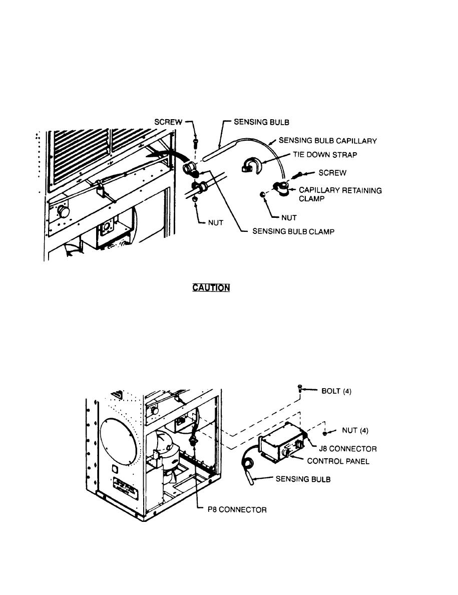
Using screwdriver and wrench, loosen screw and nut in the two loop clamps that hold the sensing bulb and
drain line.
Take care that sensing bulb capillary line is not kinked and that bulb and capillary
are not cut or damaged during removal.
g. Using screwdriver and wrench, remove screw, nut, and clamp that retain sensing bulb capillary to side casing.
h.
Using knife, carefully cut and remove plastic tie down strap.
i.
Slip sensing bulb out of clamp and carefully guide capillary line and sensing bulb down into lower compartment.
Using screwdriver and wrench, reinstall capillary retaining clamp (for possible future use) and tighten bulb and
j
drain line clamp hardware.
k.
Disconnect wiring harness connector P8 from connector J8 on the control panel.
