
TM9-4120-370-14
TO35E9-229-1
440. MODE SELECTOR (ROTARY) SWITCH (S) - Continued.
(5) Replace switch if damaged.
Test
c.
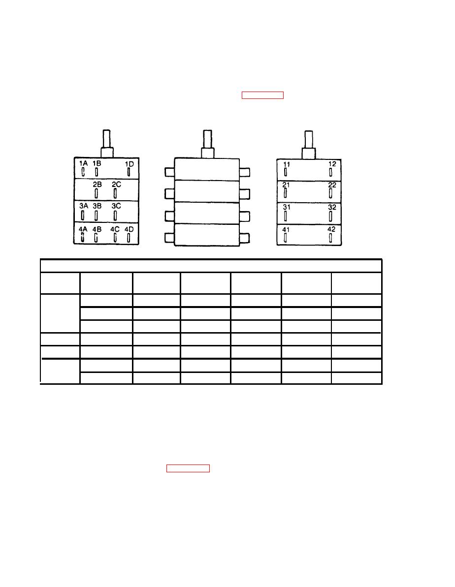
(1) Using Multimeter and switch position chart shown on Figure 4-54, check continuity at contacts indicated.
With switch position closed, continuity should be indicated. With switch position open, no continuity should
be indicated. Check between each set of contacts and at each switch position.
SWITCH POSITION
1
4
CONTACT
2
HI HEAT
NO,
LO HEAT
VENT
OFF
COOL
CLOSED
128 1A
CLOSED
OPEN
OPEN
OPEN
S/WA
128
1B
OPEN
OPEN
OPEN
OPEN
CLOSED
118 1 D
OPEN
OPEN
OPEN
OPEN
CLOSED
S/WB
228 2B
CLOSED
CLOSED
CLOSED
OPEN
CLOSED
S/WC
CLOSED
328 3A
OPEN
OPEN
OPEN
OPEN
428 4A
CLOSED
OPEN
OPEN
OPEN
OPEN
S/WD
418 4C
CLOSED
OPEN
OPEN
OPEN
OPEN
(2) Replace switch if it fails above test.
d.
Removal. (Assuming switch has been pulled from box for above test.)
(1) Tag and disconnect leads.
(2) Remove switch.
Installation
e.
(1) See tags and wiring diagram, Figure 4-20, and connect leads.
(2) Slip switch into control box and place shaft through hole.
(3) Using wrench and holding backside of switch, secure switch to box with lock washer and nut. Be sure that
switch positions match front plate.
(4) Insert rear panel into box and aline holes.
(5) Using screwdriver and wrench, secure rear panel with four screws and nuts.
