TM 9-4120-370-14
TO 35E9-229-1
4-65. SAFETY CONTROL BOX ASSEMBLY - Continued,
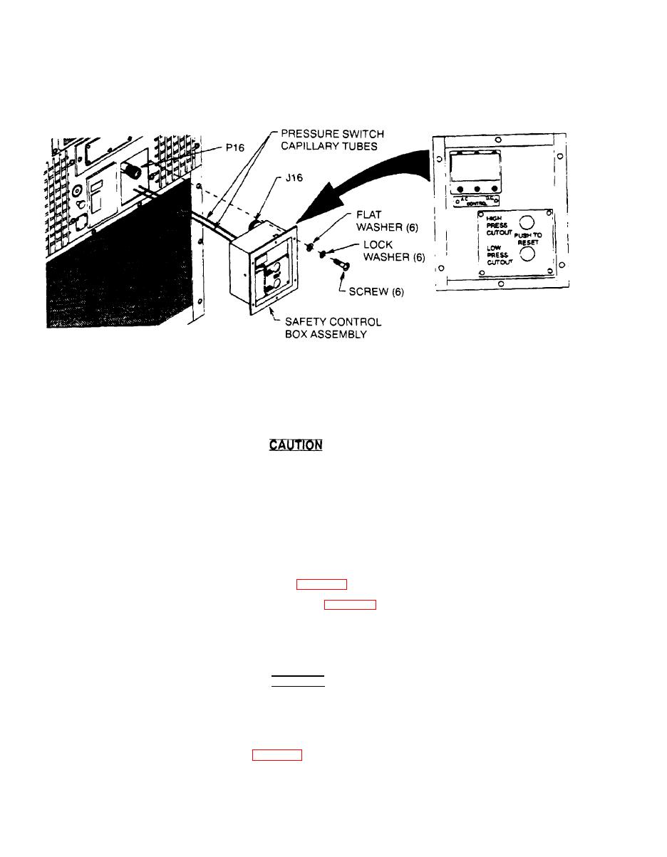
(3) Using screwdriver, remove six screws, lock washers, and flat washers from safety control box mounting
flange,
(4) Disconnect P16 connector and harness from back side of box.
Take care that pressure switch capillary tubes are not damaged.
(5) Carefully slip safety control box out of unit far enough to gain access to safety control panel mounting
screws.
(6) Support safety control box so that pressure switch capillary tubes will not be damaged.
(7) If safety control box is to be totally removed, contact direct support maintenance for pressure switch discon.
nection.
For inspection, test, and removal of internal parts see:
b.
Safety control box wiring harness (para 4-66)
Control circuit breakers (CB2 and CB3) (para 4-67).
Z
For the HIGH and LOW PRESSURE CUT OUT switches contact direct support maintenance.
Installation
c.
(1)
Connect P16 connector and harnesstoJ16 connector on back side of box,
CAUTION
Take care that pressure switch capillary tubes are not damaged.
(2)
Carefully slip safety control box back into unit and aline mounting holes.
(3)
Using screwdriver. secure safety control box to unit with six screws, lock washers, and flat washers,
(4)
Install lower front panel. (See para 4-25.)

