TM9-4120-370-14
TO35E9-229-1
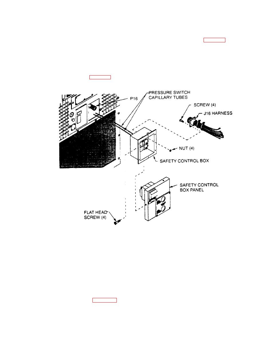
4-65. SAFETY CONTROL BOX ASSEMBLY - Continued.
(5) On models F36T-2SA and F36T-2SB install condenser air deflector door. (See para 4-26.)
(6) Connect power cable to unit.
(7) Turn power on at power source.
Pull safety control box out far enough to gain access to panel mounting screws
Preliminary procedure:
(See para 4-65.)
Inspection/Test
a.
(1) Check to see that power has been disconnected
(2) Using screwdriver, remove four flat head screws from safety control box panel
(3) Carefully pull panel from safety control box far enough to gain access to internal wire leads.
(4) Check connectors P16 and J16 for general condition and loose, broken, or missing contacts. Replace
damaged connectors.
(5) Check individual wires for loose solder connections, loose terminal lug connections, cut or frayed
insulation, and cut or broken wires.
(6) See wiring diagram (Figure 4-20) and continuity test individual wires. Repair or replace wires with no

