
TM 55-4920-384-13&P
71056C
104579C
of different lengths are used but these can be proper-
ly reassembled according to the various lengths of
cylinder head bosses.
Before reassembling the cylinder head, all carbon and
lead deposits should be removed. It is recommended
that a new cylinder head gasket be used on reassem-
bly as the old gasket will be compressed and hard so
104716C-1
that it may not seal properly. Use a mixture of graphite
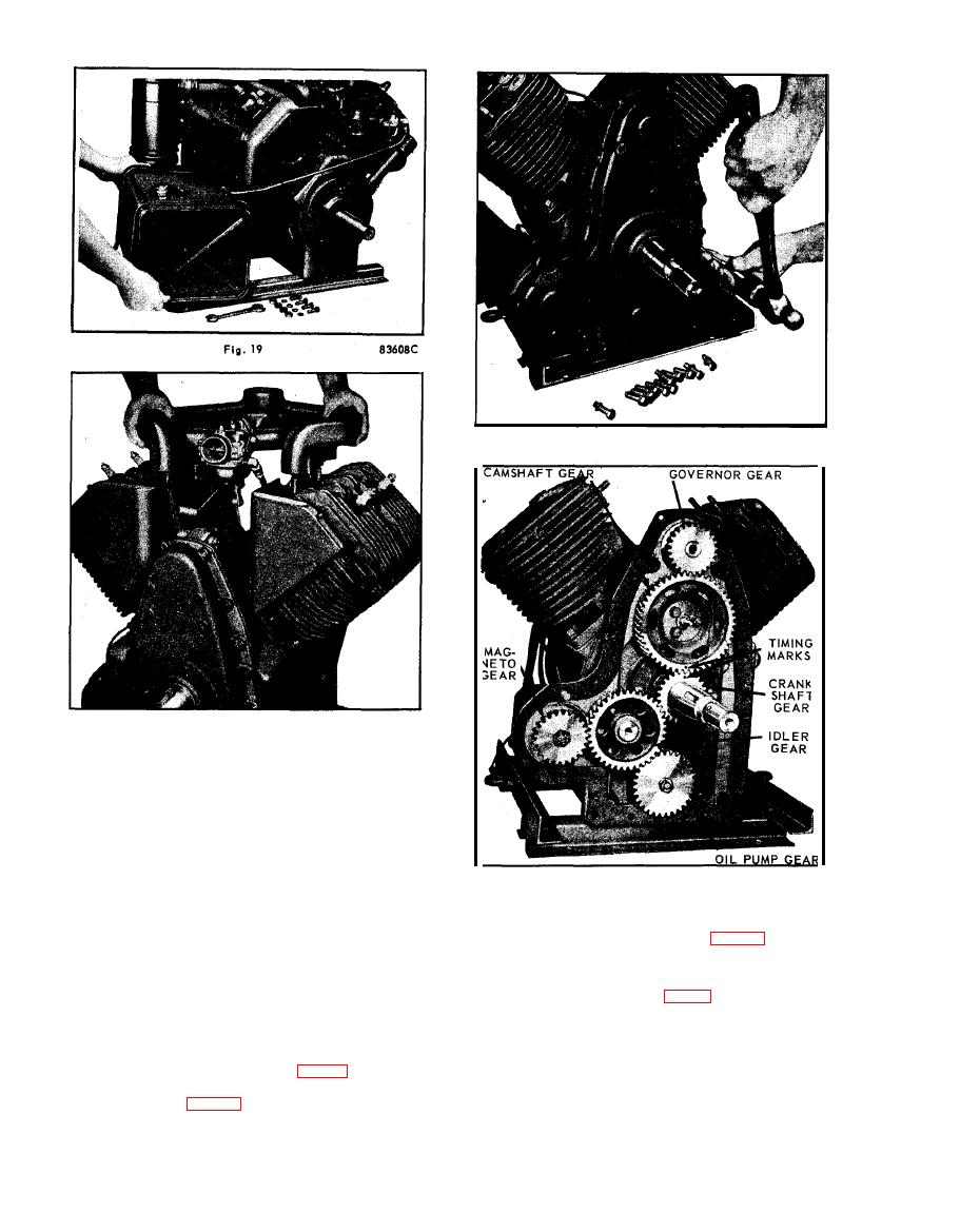
GEAR TRAIN
and oil on the cylinder head screws, to prevent them
from rusting tight against the cylinder block. Tighten
With the removal of gear cover and oil sling the gear
cylinder head screws, 25 to 32 foot pounds torque,
train will be exposed as shown in Fig. 22. Remove
and after complete assembly and engine is run in, re-
camshaft thrust plunger and spring, to prevent their
torque head screws.
being lost.
Future reference can be made to Fig. 22 when assem-
GEAR COVER
bling crankshaft and camshaft, as accurate location
of the timing marks is essential.
Disconnect the governor linkage and remove the gov-
ernor assembly. Remove gear cover screws and drive
IDLER GEAR AND SHAFT
out the two dowel pins as shown in Fig. 21. The gear
cover can then be taken off, exposing the timing
Remove the Allen-head set screw, on the magneto
gears as shown in Fig. 22. In reassembly, tighten
side of the crankcase, which locks the idler shaft
gear cover capscrews, 14 to 18 foot pounds torque.
in position. With the use of a gear puller, the idler
D-18
