
TM 55-4920-384-13&P
FULL
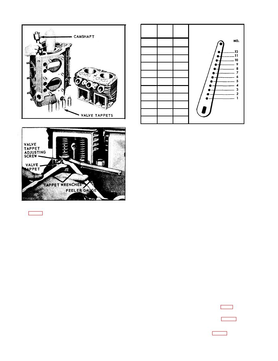
NO
HOLE
LOAD
LOAD
GOVERNOR
R.P.M.
R.P.M.
`No"
LEVER
HOLE
1550
1400
4
1650
1500
5
1725
1600
5
1700
1850
6
1950
1800
7
2050
1900
8
2125
2000
8
2250
2100
9
2200
2350
10
2425
2300
10
2550
2400
11
104569C
spring tension to suit.
GOVERNOR ADJUSTMENT
The control rod between the governor and carburetor
must be adjusted to the proper length, otherwise gov-
ernor action will be faulty. With the engine at rest
the governor spring will hold the flyweights in, and
the control rod must be of such length as to hold the
carburetor throttle wide open at that point. The ac-
curacy of this adjustment can be tested by discon-
necting the control rod ball joint from the governor
lever, and then pushing the rod assembly toward the
c a r b u r e t o r as far as it will go. This will open the
throttle wide. The governor lever should then be
180186C
m o v e d as far as possible in the same direction.
Holding both parts in the above position, the ball
joint should be screwed on to the control rod until
tions, engine cold, the clearance should be:
the right angle stud on the ball joint fitting will
Inlet Valves .008", Exhaust Valves .016"
register with the hole in the lever, then, screw fitting
in two more turns. Insert ball joint stud into the hole
GOVERNOR - OPERATION
in the governor lever, assemble and tighten locknuts.
With the governor lever pushed toward the carburetor
The centrifugal flyball governor rotates on ball-bear-
as far as it will go, there should be about a 1/16
ing supported shaft in the upper part of the timing
inch clearance between the throttle lever and the
gear cover, and the governor is driven off the cam-
stop pin on the carburetor. The clearance will cause
shaft gear at 1-1/8 times crankshaft speed.
the lever to bounce back from the stop pin, rather
The flyweights are hinged to lugs on a drive hub be-
than jam against the pin, when a load is suddenly
hind the gear. Hardened pins on the flyweights bear
applied to an idling engine. This will eliminate ex-
against the flanged sliding sleeve, moving it back
cessive wear on the threads of the control rod and
and forth as the flyweights move in or out. The motion
ball joints.
of the sleeve is transmitted through a ball thrust bear-
The governor can be disassembled from the engine by
ing to the governor lever, which in turn is connected
first removing the governor housing, after which the
to the carburetor throttle lever. A spring connected to
entire governor can be withdrawn from the gear cover.
the governor lever tends to hold the governor fly-
The constuction of the governor can be best seen
weights to their inner position, also to hold the carb-
from the sectional drawing of the engine, Fig. 3.
uretor throttle open. As the engine speed increases,
The governor lever is furnished with 12 holes for
the centrifugal force in the flyweights acts against
attaching the governor spring as shown in Fig. 35. It
the spring and closes the throttle to a point where the
is very important that the spring is hooked into the
engine speed will be maintained practically constant
proper hole to suit the speed at which the engine is
under varying load conditions. This speed can be
operated. The Governor Lever Chart, Fig. 35, s h o w s
varied to suit conditions by adjusting the governor
D-22
