TM 55-4920-384-13&P
209574C
Use a suitable ring compressor in reassembly and
stagger the piston ring gaps 90 apart around the
and cylinder walls before assembly.
CYLINDERS
The cylinder blocks can now be removed from the
c r a n k c a s e if necessary. In reassembling, put the
blocks back on the same side from which they were
removed. Clean all dirt and other deposits from fins
104819C-1
before reassembling. If the cylinders are worn more
than .005 inch oversize, they should be reground and
fitted with oversize pistons and rings.
Tighten cylinder block mounting nuts, 62 to 78 foot
pounds torque.
VALVES
Remove the valve tappet inspection plate and com-
press the valve springs with a standard automotive
type valve lifter, as shown in Fig. 31. If cylinder
block is still attached to the engine, insert a rag in
the opening at the bottom of the valve chamber so the
roto-cap and valve spring seat retaining locks do not
fall into the crankcase. Remove the roto-caps, valve
s p r i n g seat retaining locks, seats, springs, . .valves
and clean these, as well as the ports and guides, of
71152C
all carbon and gum deposits. Tag each valve so that
in reassembly they will be mounted in the same guide
the engine, be sure the arrow on the top of the piston
they were removed from.
is pointing in the direction of crankshaft rotation.
(Clockwise when viewing the flywheel end of the en-
Non-positive type roto-caps are provided on the ends
gine). See Engine Sectional, Fig. 3.
of the valve stems. In reassembly, be sure to assem-
ble the roto-caps to the end of the valve stems.
Tighten connecting rod nuts, 28 to 32 foot pounds
torque, then install `Pal' locknuts and tighten with
The valve face is ground at 45 to the vertical cen-
wrench 1/4 turn beyond `finger-tight' position.
ter line of the valve stem and the valve seat insert
should also be ground at a 45 angle. After grinding
Be sure piston and connecting rod assemblies are
valves and inserts should be lapped with a suitable
put back into the same bore from which they were
lapping compound or they will leak due to improper
removed.
seating within the first few hours of operation. After
PISTON RINGS
valve seats have been cleaned, apply lapping com-
pound to the valve face and put the valves back into
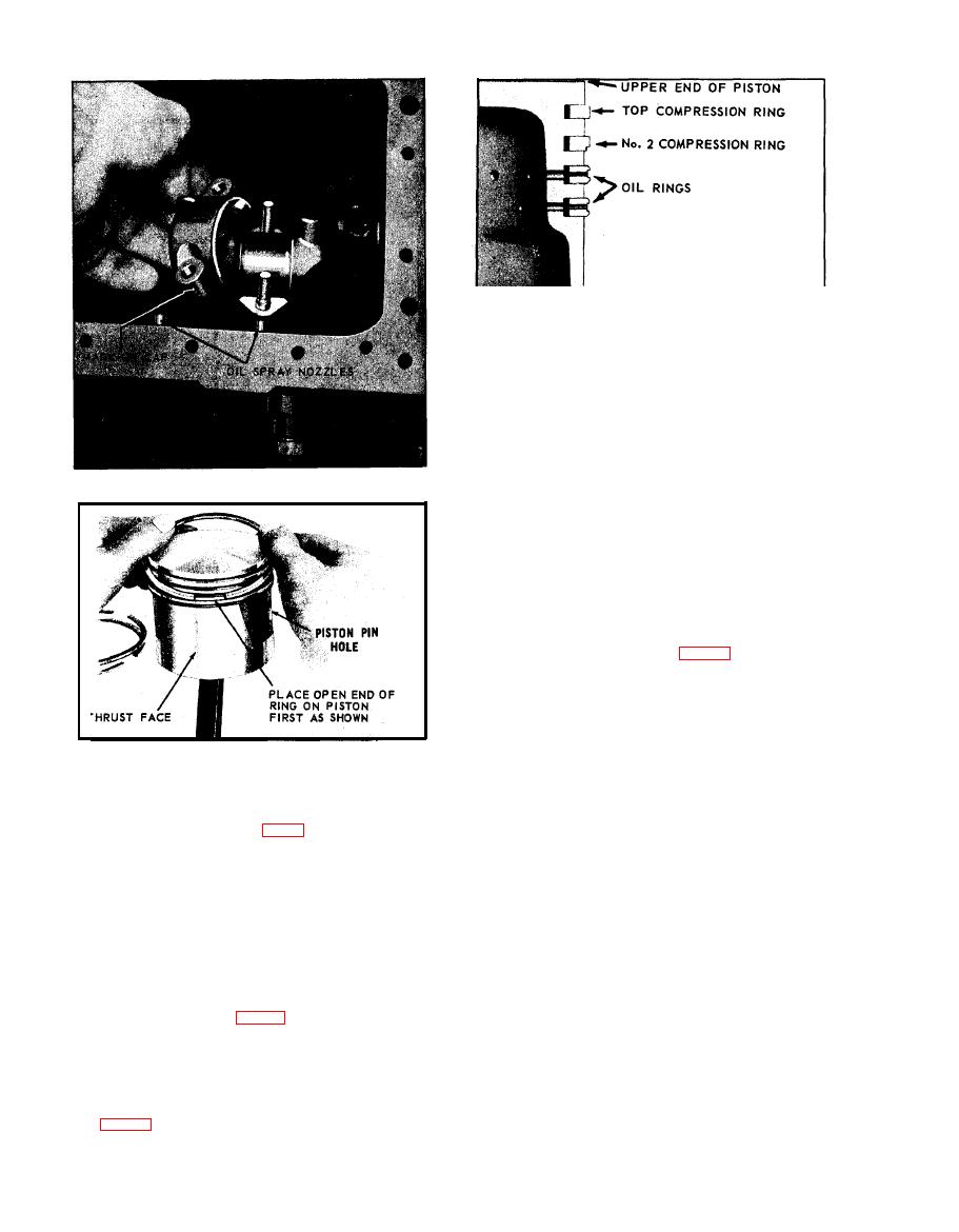
Install rings by placing the open end of the ring on
their guides. Lap the valves by rotating them back
piston first, as shown in Fig. 28. Spread ring only far
and forth with a reciprocating advancing valve tool.
enough to slip over piston and into correct groove,
O c c a s i o n a l lift the valves and reseat them in a
being careful not to distort ring.
different position to insure a uniform seat which will
The Number 2 compression ring must be installed on
show entirely around the valves. After valves have
the piston with the scraper edge down, otherwise oil
been lapped in evenly, remove them from the block
pumping and excessive oil consumption will result,
and wash the valves and block thoroughly with gaso-
See Fig. 29.
line or kerosene.
D-20

