
TM 9-2330-285-14&P/TO 36A11-21-10-1
FRONT AXLE BEAM - CONTINUED
ACTION
LOCATION
ITEM
REMARKS
INSTALLATION
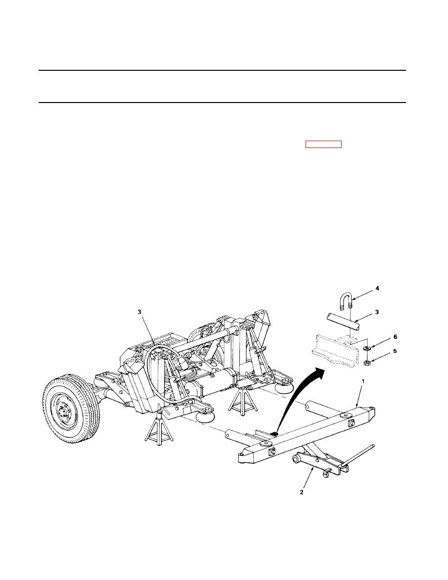
4 Floor under front
Axle beam (1)
a. Position parts for installation.
of dolly set
and hydraulic
b. Install axle arms (page 4-78).
floor jack (2)
c. Raise axle beam (1) into position using
hydraulic jack (2).
5 Front axle beam
U-bolt (4), two
Secure intervehicular cable (3) with U-bolt
(1) to inter-
nuts (5) and
(4), two nuts (5) and two washers (6) using
vehicular cable (3)
two washers (6)
a 7/16-inch wrench.
6 Front axle beam (1)
Hydraulic floor
a. Raise the dolly set off of two jackstands
jack (2) and two
(3) using hydraulic floor jack (2) under
jackstands (3)
the front axle beam (1).
b. Place the jackstands (3) under the front
axle beam (1).
c. Lower the dolly set onto jackstands (3).
TA 221702
