
TM 9-2330-356-14
(13) Repeat steps (8) through (12) for other side.
(5) Remove jacks from under trunnion cross
tube. Raise semitrailer another 16-inches, or until there is
(14) Slowly lower axle.
enough clearance to roll the bogie assembly and wheels
out from under rear of semitrailer (fig. 5-6).
b.
Installation (Fig. S-S).
(6) Lower semitrailer onto supports or cribbing
(1) Move axle into position under semitrailer.
after bogie assembly is removed (fig 5-3).
Raise and revolve axle into position on ends of suspension
springs.
(2) At each end of axIe, loosely install spring
seats, adjustment plates, cushioning pads, and spring end
caps with two U-bolts, four washers, and four nuts.
(3) At each end of axle, loosely install spring end
cap to spring seat on axle with four bolts, four washers, and
four nuts.
(4) Tighten all nuts evenly to 200-320 lb.-ft.
(5) Install brake air chambers (para 4-38).
(6) Install wheels (para 4-49).
(7) Remove supports and jacks.
(8) Tighten wheel nuts to proper torque and in
proper sequence (pars 4-49).
b.
Installation.
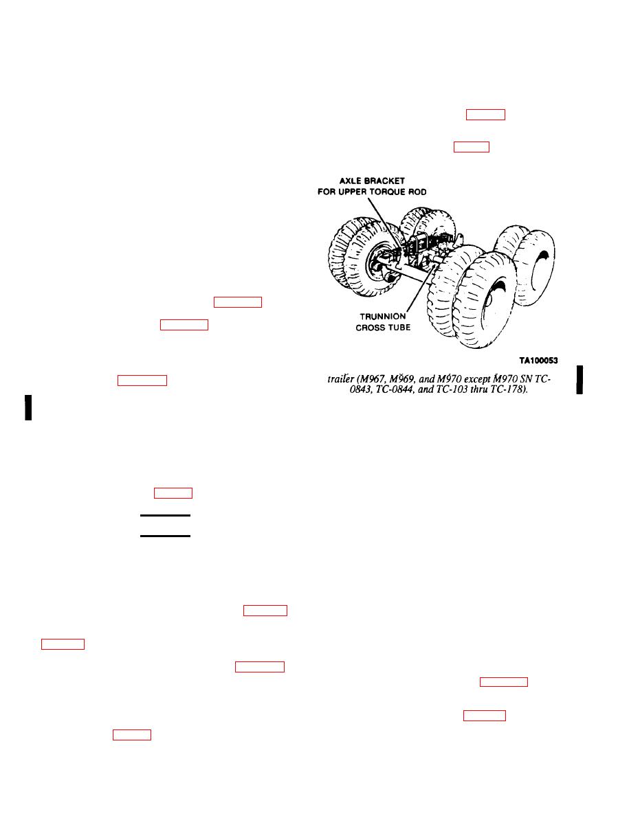
except M970 SN TC-0843, TC-0844, and TC-103
thru TC-178).
a.
Removal.
NOTE
The upper torque rods on the front and rear
(1) Position semitrailer on hard, level surface
axles will be toward the right aide (curbside)
with front resting on landing gear. Raise rear of
of the semitrailer If the bogie assembly Is
semitrailer with an overhead crane or A-frame support
installed correctly.
until all wheels are approximately l-inch off the ground.
Block the frame securely (fig. 5-3).
(1) Raise rear of semitrailer to allow bogie
assembly to roll under frame from rear. With front of
WARNING
bogie assembly toward front of semitrailer, roll bogie
assembly into position under support brackets for
Release air pressure from both air reservoirs
trunnion cross tube.
before doing any work on brake lines or other
pressurized air lines.
(2) Lower the semitrailer to within 1-inch of the
trunnion cross tube bracket. Ensure that the holes of the
support brackets are in line with holes in trunnion cross
(2) Release air from both air reservoirs by
tube bracket.
opening drain cocks on bottom of reservoirs (fig. 4-79).
Tag and disconnect eight hoses from brake air chambers
(3) Install eight bolts, washers, and nuts. As you
on both axles. Manually release the fail-safe springs
tighten the nuts, jack up the trunnion cross tube brackets
to seat the support brackets. Tighten nuts to
450-650 lb.-ft. Remove jacks.
(3) Remove two upper torque rods (para 5-11).
(4) Install upper torque rods (para 5-11).
(4) Position jacks under mounting brackets of
trunnion cross tube (one jack under each bracket) to
(5) Connect hoses to brake chambers as tagged.
support weight of trunnion cross tube. Remove four nuts,
Manually release fail-safe springs (pars 2-4).
washers, and bolts which fasten each mounting bracket to
support bracket (fig. 5-3).
(6) Remove supports and jacks.
Change 3
