TM 9-2330-356-14
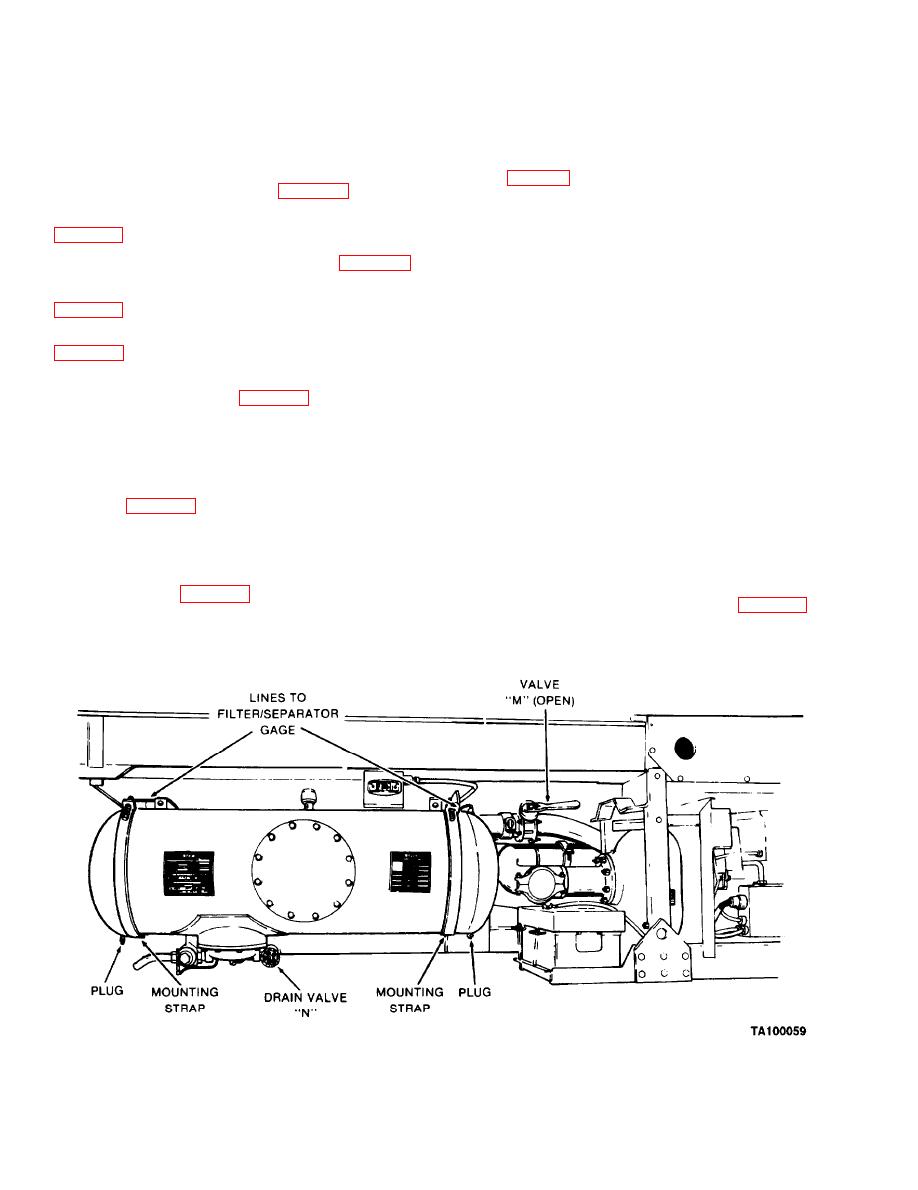
(2) Open drain valve Non sump to remove fuel
(4) Install two capscrews (25), lockwashers (24),
and sediment from filter/separator. Also remove drain
and nuts (23) to fasten fan shroud (22) to base frame.
plugs on bottom of filter/separator.
(5) Fasten rear firewall sections (14 and 12) to
(3) Tag and disconnect four lines from filter
rear panel (6) with two screws (13) and nuts (5).
separator (fig. 5-12).
(6) Install pump assembly (para 5-19).
(4) Remove split couplings from inlet and outlet
(7) Install fuel lines to fuel tank and engine
lines at filter/separator.
(5) Position either lift truck forks or dolly jack
(8) Install muffler and exhaust pipe (para 4-77).
under filter/separator to take up weight. Use care not to
damage sump components. Remove four nuts and
cleaner and intake hose
(9) Install air
washers from mounting straps. Remove mounting straps
and webbing. Remove filter/separator.
(10) Install wiring harness and electrical leads
b.
Installation.
(1) Position filter/separator at center of two
(11) Ensure that engine crankcase is filled to
mounting brackets with drain valve at bottom and service
proper level with correct oil (para 4-71).
port opening toward outboard side.
(12) Install top panel (26) to panels (6 and 7).
(2) Position webbing on mounting straps. Install
Secure with ten capscrews (27), twenty washers (28), and
mounting straps with washers and nuts. Tighten nuts to
ten nuts (29).
142-158 lb.-ft.
(13) Install engine and pump module on
(3) Connect four lines for filter/separator as
semitrailer (para 5-18).
tagged. Two lines for filter/separator gage are connected
to elbows at front and rear of filter/separator. Fuel line is
(14) Install capscrews (9) and nuts (10) for the rear
connected to elbow at top of filter/separator. Pilot line is
cross brace.
connected to control valve on sump.
Filter/Separator (M969, M969A1, M970, and
5-21.
(4) Install split couplings to connect
M970A1) (Fig. 5-12)
filter/separator inlet and outlet to tank piping (para 4-85).
Tighten two bolts on split couplings to 95-105 lb.-ft.
Removal.
a..
(5) Close drain valve N and open valve M.
(1) Close valve M on curbside of semitrailer.
5-26


