
TM 9-2330-356-14
Installation.
(2) Position meter assembly in cabinet. Ensure c.
that spacers are in position under meter. Install three
mounting screws and washers from under cabinet.
(1) Observe all applicable warning/safety
precautions (inside front cover and safety summary).
(3) Install split couplings (para 4-85). Tighten
(2) Refer to paragraph 4-85 for general
couplings to 57-63 lb.-ft.
information on maintenance of dispensing equipment.
(3) Close meter shut-off valves P or R, and drain
(M969 and M969A1)
fuel from fuel hoses (fig. 5-15).
a.
General.
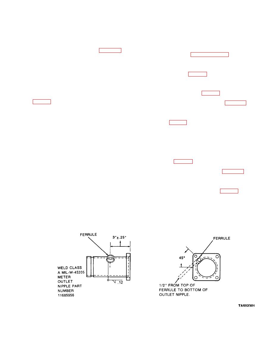
(4) Scribe location of opening to be drilled in
meter outlet nipple approximately 3-inches from the
(1) The Aqua-Glo probe and adapter may be
flanged end on a 45 angle (fig. 5-16).
installed on the meter outlet nipple of either meter
..
(5) Remove meter outlet nipple (para 5-25) and
flush thoroughly with water to eliminate fumes.
(2) The installation provides a port downstream
of the filter/separator to draw fuel samples for water
(6) Fabricate ferrule from aluminum rod
(Aqua-Glo) test.
6061-6063 (fig. 5-17).
(7) Drill a -inch diameter hole in the meter
(3) Refer to TM9-237 for information on welding
outlet nipple as described in step (4).
procedures to be followed.
(8) Insert ferrule into meter outlet nipple
Materials and Parts.
b.
approximately -inch. This will allow the assembled
probe to extend approximately halfway into the meter
(1) Probe and adapter assembly, NSN 4930-01-
outlet nipple (fig. 5-18). Weld ferrule in place.
013-7589.
(9) Install meter outlet nipple (para 5-25).
(2) Aluminum rod, alloy, 6061-6063, for fabrica-
tion of ferrule.
(10) Use thread sealing compound and install
Aqua-Glo probe and adapter. Tighten until the probe
(3) Aluminum welding rod compatible with alu-
angle is in line with direction of flow (fig. 5-18).
minum alloy, 6061-6063.
(11) Check for fuel leaks. No leaks are permitted.
(4) Thread sealing compound, NSN 8030-01-
009-2590.
(12) Paint adapter and reworked areas.
