TM 9-4110-255-14
4-37. PUSH SWITCHES S9 AND S10 TESTING AND REPLACEMENT . - Continued
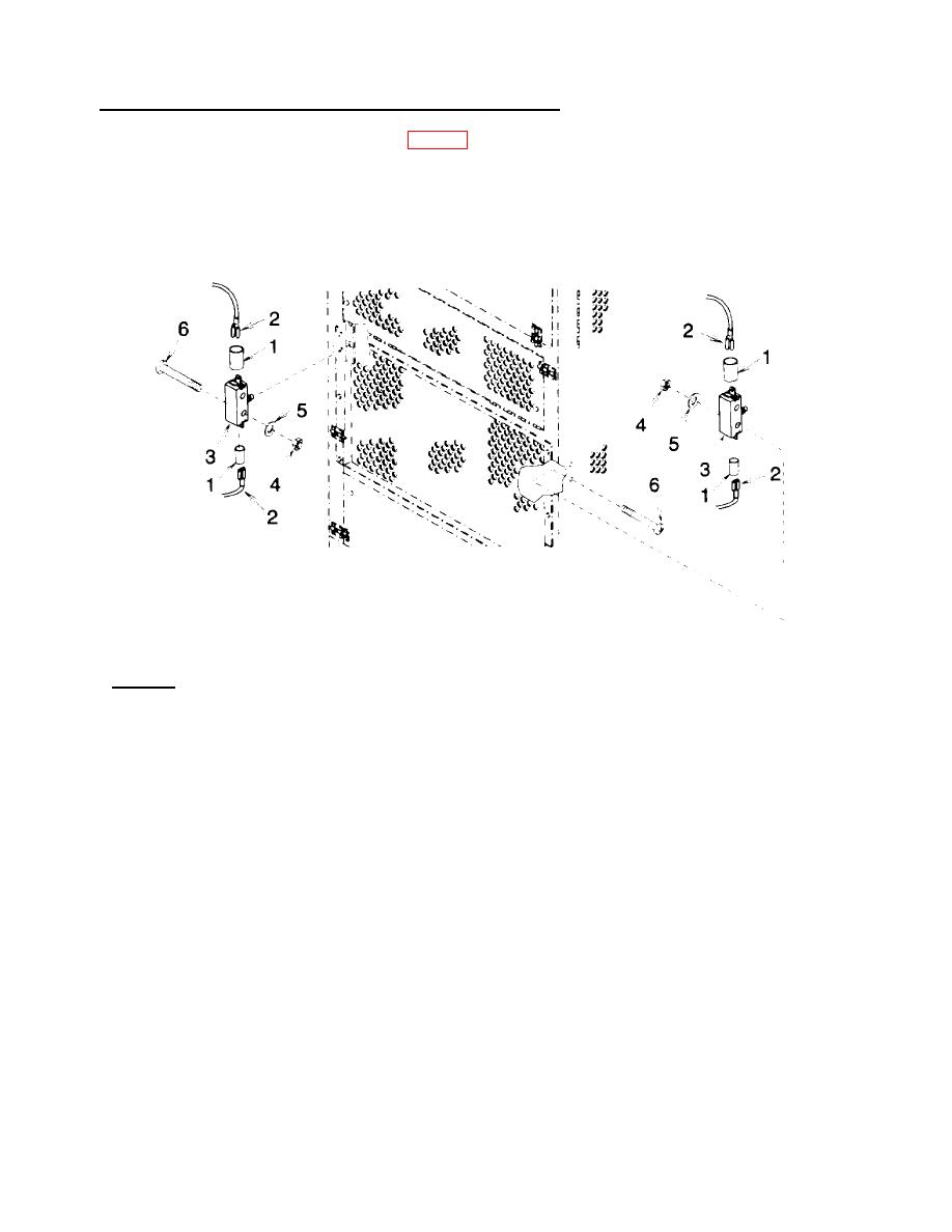
(5) Using tags and wiring diagram (fig. 1-4), connect wire leads (2). Remove tags.
NOTE
Sleeving insulation covers only terminal C on one side of push switch, but must cover both
terminals NO and NC on the other side.
(6) Slip sleeving insulation (1) over exposed terminals and shrink in place using heat gun.
Figure 4-31. Push Switches
b. Removal.
(1) Remove sleeving insulation (1).
(2) Tag and disconnect wire leads (2).
(3) Remove two self locking nuts (4), flat washers (5), bolts (6), and push switch (3). Discard self locking
nuts.
4-96


