GRINDING with REFACER ATTACHMENTS
As the preliminary step, a micrometer feed bar
supplied with the attach-
ment must be assembled to the valve refacer at the right side of the wheel-
head (after having first removed the plug in the wheelhead by striking it
sharply with a hammer directly on center - thus causing the plug to become
loose in the hole). The micrometer feed bar
is then inserted into the socket
of the wheelhead casting, turning the flat face of the spindle until it is facing
the set screw for the spindle socket. The spindle is then slid into its socket
until it bottoms; and then fastened in place with the set screw. Be sure that
the spindle collar fits snugly against the bottom of the counterbore in the
wheelhead housing.
DRESSING the ATTACHMENT WHEEL-
Clamp the diamond in the V-way by means of the quick-
clamp.
The flat, recessed side of the wheel is dressed by feed-
ing the diamond forward to contact this face through means
of the nut; and, with wheel running, moving the bracket
back and forth (fast swing for rough, slow swing for smooth
surfaces). The dressing cuts should be about .002''deep
and are controlled by calibrations in thousands of an inch
on the nut. The wheel should be dressed until the entire
face has been trued.
MICROMETER VALVE STEM GRINDING-
Avoids hit or miss grinding - to give this operation the same precision used
in the valve reconditioning work itself, and to save valuable time - use the
which accurately measures
V a l v e Stem Grinding Attachment,
(in thousandths) the amount to be ground from each valve stem, and then just
as accurately measures (in thousandths) the grinding operation itself.
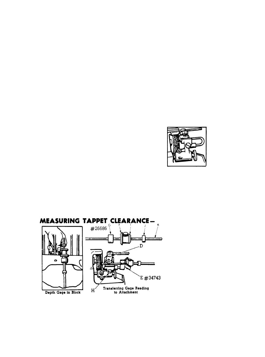
Square tappets be-
fore measuring for
t a p p e t clearance
with Depth Gage
The
universal
depth gage
is
equipped with cor-
rect size valve-head
patterns and bush-
ings for Ford re-
movable guide en-
gines. Valve-head
(F) is for Ford A
and V8-85; bushing
(G) is for Ford V8-85
valve - guide hous-
ing: valve head (I) is for Ford V8-60 valve seat; and bushing (J) is for V8-60
valve-guide housing. The valve-guide bushings are, of course, removed from
10

