
TM 9-2330-356-14
(d) Repair minor damage to the cylinder
tool. Allow valve guide to remain 0.3437-inch from top of
head castings using a fine file, emery cloth, or crocus cloth
cylinder head.
(item 4, Appendix E) dipped in dry cleaning solvent
(d) Ream the replacement valve guide, if
(item 11, Appendix E). Repair minor damage to threads
necessary, to obtain proper valve stem-to-valve guide
using a proper size tap. Do not enlarge the threaded hole.
clearances shown in table 7-2.
If minor damage cannot be repaired, replace cylinder head
casting (16) and valve seats (7). Salvage all other usable
(e) Inspect valve (8 and 10, fig. 7-55) for
components.
warped stem, pitting, evidence of burning and excessive
wear. Replace valves if badly damaged or if valve stem is
(e) Inspect studs (11) for stripped or worn
worn beyond tolerances shown in table 7-2.
threads, or a bent or loose connection. Replace studs if
damaged, using anti-seize compound (item 5, Appen-
dix E). Tighten rocker arm studs to 35-40 lb.-ft.
CAUTION
(2) Valve Guide and Valve.
If grinding on valve face produces a valve
with a thin edge, replace with a new valve.
(a) Check for valve stem-to-valve guide
allowable clearance by measuring inside diameter of valve
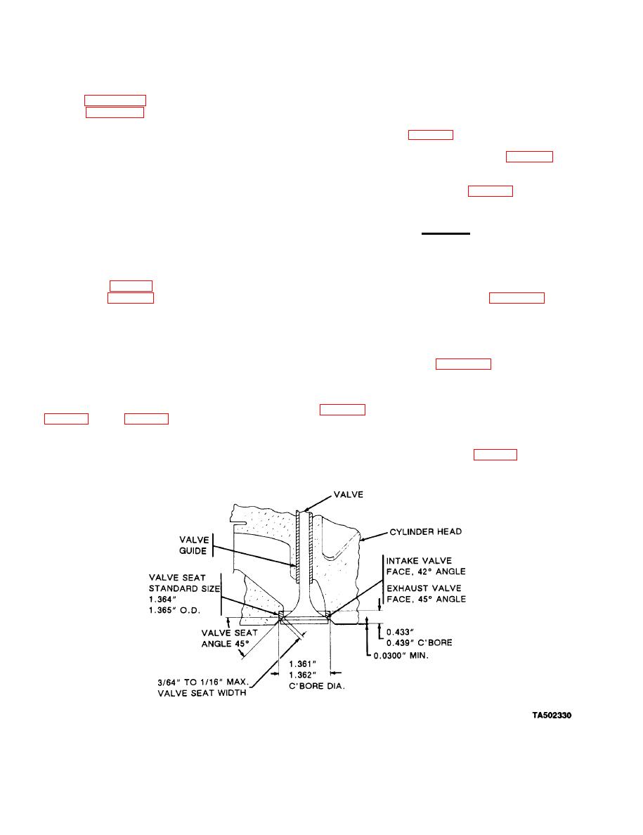
(f) Repair valves that can be refaced
guide (6 and 9, fig. 7-55) and outside diameter of the valve
grinding to the requirements shown in figure 7-56.
stem. Refer to table 7-2 for correct dimensions.
(3) Valve Seat.
NOTE
(a) Inspect valve seats. Reface valve seats if
If valve stem Is worn below minimum toler-
seat face is slightly pitted, burned, or worn and can be
ances, replace the valve. If new valve fails to
refaced to requirements in figure 7-56. If valve seats are
correct stem-to-valve guide clearance, re-
loose, they must be replaced as follows:
place valve guide.
(b) Secure valve seat remover cutter tool
(b) Using Correct size valve guide driver tool
1/64-inch from outside edge of valve seat.
(c) Install new replacement valve guide
(c) Apply oil to pilot end of cutting tool to
through top of cylinder head using the valve guide driver
prevent seizing in the valve guide (fig. 7-55).
