TM 9-4120-370-14
TO 35E9-229-1
5-18. HIGH PRESSURE CUTOUT SWITCH (S5) - Continued.
(7)
Carefully coil excess capillary tubing and tape in place to eliminate vibration.
Replace the dehydrator. (See para 514.)
(8)
Leak test all newly connected joints and those in the repaired area. (See para 510.)
(9)
(10) Using screwdriver, secure the safety control box panel to the box with four flat head screws.
(11) Insert safety control box into unit taking, care that capillary tubing is not damaged.
(12) Connect P16 connector and harness to J16 connector on back of box.
(13) Using screwdriver, secure the safety control box to the unit with six screws, lock washers, and flat washers.
(14) Set the bottom of the lower front panel in position so that the flange is inside the lip on the cabinet base.
(15) Push the top of the panel back into position.
(16) Using screwdriver, tighten the five captive panel screws in the lower front panel.
(17) Evacuate and charge the refrigerant system. (See para 511 and para 512.)
Followon procedures:
1. On F36T2SA and F36T42SB install condenser discharge air deflector door. (See para
2. Connect power.
3. Press and release pressure switch reset buttons to be sure they are not tripped.
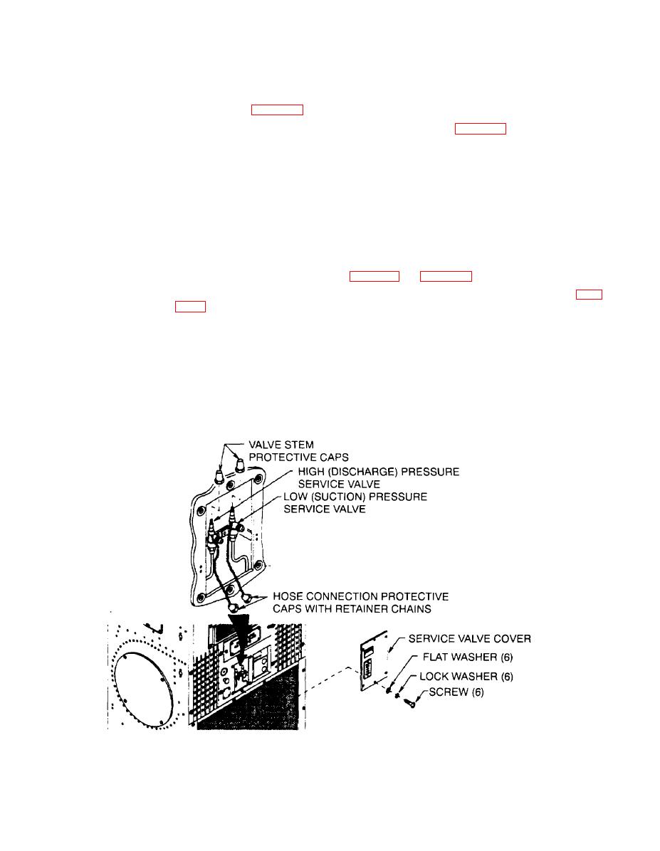
5-19. SERVICE VALVES
a. Access
(1) On F36T-2SA and F36T4-2SB open condenser discharge air deflector door.
(2) Using screwdriver, remove six screws, lock washers, and flat washers from service valve cover.

